
RC Robot Tank
My project is a RC Robot Tank where I controlled an Arduino through my own programming. The Arduino is connected to a my self built controller and a motor to control the movement of the tank. And finally, I built a tank frame by putting smaller and cute pieces together, holding everything in.
Engineer
Duly O
Area of Interest
Robotics
School
KIPP NYC College Prep
Grade
Incoming Junior
Relection
My time here at Bluestamp Engineering was a rollercoaster. I had many days which I felt annoyed and behind especially with my starter project. I had to do multiple starter projects and I was always rushing due to seeing my peers starting on their main projects. After many tries and struggles, I knew that focusing on my peers achievements would not get me anywhere. I decided to focus on myself. After I finally finished my starter project, I was filled with joy and ready to start my main project. However, the same feeling of being behind came and the pattern of me slowing down came back. With the help and support of the instructors, my mindset and work ethic changed. I started to be more patient and take my time with my project.I felt more accomplished and felt that I was on track finishing my project along with my friends. As the weeks got closer to 6th, I became much more positive and optimistic, not only for my own accomplishments but also for my peers. Clapping and cheering them as loud as I could, showing support for their achievements. I came across hundreds of problems, and received help from all of the instructors. Through this program, I really realized that asking for help and guidance isn’t a problem at all.Being hard on yourself just slows yourself down and sets a bad mindset, stunting growth and flourishment .This program allowed me to flourish in an independent environment where I developed problem solving skills. I pushed myself to be more independent, work hard, and feel set up for life. After this program, I will not only walk away with work ethic skills but my experience in engineering. I can now apply these skills and portfolio for any program or college that I am interested in. Through Bluestamp Engineering, I opened more doors for me and revealed more opportunities . I cannot wait to see where engineering takes me!
Final Milestone
Custom controller and the robot tank

/*
* Arduino Wireless Communication Tutorial
* Example 1 - Receiver Code
*
* by Dejan Nedelkovski, www.HowToMechatronics.com
*
* Library: TMRh20/RF24, https://github.com/tmrh20/RF24/
*/
#include <SPI.h>
#include <nRF24L01.h>
#include <RF24.h>
RF24 radio(7, 8); // CE, CSN
const byte address[6] = "00001";
bool arr[4];

//The directions in which the motors go
int in1 = 9; //Declaring the pins where in1 in2 from the driver are wired
int in2 = 10;//was 8, dark blue wire //here they are wired with D9 and D8 from Arduino
int ConA = 3;//was 10, yellow wire with green writing
int in3 = 4;//was 13, purple wire
int in4 = 2;//was 12, dark green wire
int ConB = 5;//Was 11, orange wire
//And we add the pin to control the speed after we remove its jumper

void setup() {
Serial.begin(9600);
radio.begin();
radio.openReadingPipe(0, address);
radio.setPALevel(RF24_PA_MIN);
radio.startListening();
radio.setChannel(99);//different frequency


pinMode(in1, OUTPUT); //Declaring the pin modes, obviously they're outputs
pinMode(in2, OUTPUT);
pinMode(ConA, OUTPUT);
pinMode(in3, OUTPUT);
pinMode(in4, OUTPUT);
pinMode(ConB, OUTPUT);
}

//void TurnOFFA(){
// digitalWrite(in1, LOW);
// digitalWrite(in2, LOW);
// digitalWrite(ConA,LOW);
//}
//void TurnOFFB(){
// digitalWrite(in3, LOW);
// digitalWrite(in4, LOW);
// digitalWrite(ConB,LOW);
//}

//Forward
void Forward(){
digitalWrite(in1, LOW);
digitalWrite(in2, HIGH);
digitalWrite(in3, LOW);
digitalWrite(in4, HIGH);
digitalWrite(ConA,HIGH);
digitalWrite(ConB,HIGH);

}

//Backward
void Backward(){
digitalWrite(in1, HIGH);
digitalWrite(in2, LOW);
digitalWrite(in3, HIGH);
digitalWrite(in4, LOW);
digitalWrite(ConA,HIGH);
digitalWrite(ConB,HIGH);

}


//Left
void Left(){
Serial.println("Left");
digitalWrite(in1, LOW);
digitalWrite(in2, HIGH);
digitalWrite(ConA,HIGH);
digitalWrite(in3, HIGH);
digitalWrite(in4, LOW);
digitalWrite(ConB,HIGH);
// TurnOFFA();
//delay(2000);
// TurnOFFB();

}
//Right
void Right(){
digitalWrite(in1, HIGH);
digitalWrite(in2, LOW);
digitalWrite(ConA,HIGH);
digitalWrite(in3, LOW);
digitalWrite(in4, HIGH);
digitalWrite(ConB,HIGH);

}


// if(left == 1 && right == 0 && forward == 0 &&)


void loop() {
if(!radio.available()){
Serial.println("No connection");//If
}
// if (radio.available()) {
// Serial.print("Connected: ");
// char text[32] = "";
// radio.read(&text, sizeof(text));
// Serial.println(text);

radio.read(&arr, sizeof(arr));
Serial.print("Connected: ");

bool left = arr[0];
bool right = arr[1];
bool forward = arr[2];
bool backward = arr[3];

Serial.print(forward);Serial.print(backward);Serial.print(left);Serial.println(right);
delay(1);//


//bool left = arr[0];
//bool right = arr[1];
//bool forward = arr[2];
//bool backward = arr[3];

if(left == 0 && right == 1 && forward == 0 && backward ==0){//If right is pressed then the tank will move left
Right();
}

if(left == 1 && right == 0 && forward == 0 && backward ==0){//IF left is pressed then the tank will move left
Left();
}

if(left == 0 && right == 0 && forward == 1 && backward ==0){//if forward is pressed then the tank will move forward
Forward();
}

if(left == 0 && right == 0 && forward == 0 && backward ==1){//if backward button(blue) is pressed then the co
Backward();
}

if(left == 0 && right == 0 && forward == 0 && backward ==0){//if code no buttons are pressed then the motors shut down
digitalWrite(in1, LOW);
digitalWrite(in2, LOW);
digitalWrite(ConA,LOW);
digitalWrite(in3, LOW);
digitalWrite(in4, LOW);
digitalWrite(ConB,LOW);
}

}
/*
* Arduino Wireless Communication Tutorial
* Example 1 - Transmitter Code
*
* by Dejan Nedelkovski, www.HowToMechatronics.com
*
* Library: TMRh20/RF24, https://github.com/tmrh20/RF24/
*/
#include <SPI.h>
#include <nRF24L01.h>
#include <RF24.h>
RF24 radio(7, 8); // CE, CSN
const byte address[6] = "00001";

bool left = 0;
bool right = 0;
bool forward = 0;
bool backward = 0;

bool arr[4];

void setup() {

Serial.begin(9600);
radio.begin();
radio.openWritingPipe(address);
radio.setPALevel(RF24_PA_MIN);
radio.stopListening();
radio.setChannel(99);

int red = 5;
int blue = 4;
int yellow = 3;
int black = 2;

pinMode(red,INPUT);
pinMode(blue,INPUT);
pinMode(yellow,INPUT);
pinMode(black,INPUT);
}

void loop() {

left = digitalRead(3);
right = digitalRead(2);
forward = digitalRead(5);
backward = digitalRead(4);

arr[0] = left;
arr[1] = right;
arr[2] = forward;
arr[3] = backward;

Serial.print(arr[2]);Serial.print(arr[3]);Serial.print(arr[0]);Serial.println(arr[1]);
radio.write(&arr, sizeof(arr));
delay(1);


// const char text[] = "Hello World";
// radio.write(&text, sizeof(text));
// delay(1000);

}
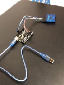
Wiring for NRF to Arduino and Nano

I finished my final project! For my final project, I created my own Bluetooth controller using NRF connecting my to my robot tank. Firstly, I proceeded to get a Nano which is a smaller version of an arduino so that I can have a small controller and have , being the brain of the controller. I then used two NRF’s to connect to my Arduino Uno and Nano so that I can secure a Bluetooth connection. I soldered row of pins onto the Nano so I can then help connect my Nano to the NRF and with the help of How to Mechatronics, I connected the NRF’s to the Arduino and Nano. An NRF helps facilitate a bluetooth connection through sending signals at certain frequencies.
Flow chart of code for receiver and transmitter

I started to rewire my pins for the motors because my NRF required certain pins. This resulted in me changing some of my code. Using a sample code from the website above, I attempted to send messages to my receiver from the transmitter.
The system works in the following manner:
- The Nano transmitter listens to a button press
- Nano transmitter NRF sends button press to Uno receiver NRF
- The Arduino reads which button is pressed and moves
This at first wasn’t hard at all but I had to constantly rewire and change the ports when uploading the code to the Nano and the Arduino. I experimented with sending messages between the NRF’s to make sure I knew it worked. After successful sending “Yo its Duly”, it all of a sudden stopped working but after another student started claiming that “Yo its Duly” started to print in her serial monitor, my instructor recommended me to change my frequency so I would not interfere with any of my peer’s projects. Add a picture somewhere before this or reference the pictures you do have somewhere before this just to draw attention to the graphic. After that I started on developing my board where my prototype controller will sit and where i will control the direction in which the tank moved and its speed. I started with adding four buttons which have different colors so I can differentiate each button from each other. I then started to add pins for the Nano onto board where the pins of the buttons were connected to , so I can control the Nano to my board. I continued and connected both of the grounds of the bread board together so that there was an imbalance of voltage. Using 4 800 ohm resistors, it secured a zero voltage board when the board is not in use. My main focus after that was to connect my buttons to Nano to Arduino. Since buttons are basically switches, either on or off, I used booleans so I can define and function the pins, therefore controlling what the button says or does when pressed. I was able to make my Nano print either 1,10,100,1000 for each button when it was pressed onto the serial monitor and print that onto my receiver, allowing my buttons to control what is printed. I defined the colored buttons as forward for red, blue for backward, yellow for left and black for red. I then put my code for my directions onto the receiver and coded a series of if statements stating whether if a button is pressed and the others aren’t then it will move.
Third Milestone
The robot tank with an off switch

//The directions in which the motors go
int in1 = 9; //Declaring the pins where in1 in2 from the driver are wired
int in2 = 0;//was 8, dark blue wire //here they are wired with D9 and D8 from Arduino
int ConA = 10;//was 10, yellow wire with green writing
int in3 = 1;//was 13, purple wire
int in4 = 2;//was 12, dark green wire
int ConB = 5;//Was 11, orange wire
//And we add the pin to control the speed after we remove its jumper
//Make sure it's connected to a pin that can deliver a PWM signal
void setup() {
pinMode(in1, OUTPUT); //Declaring the pin modes, obviously they're outputs
pinMode(in2, OUTPUT);
pinMode(ConA, OUTPUT);
pinMode(in3, OUTPUT);
pinMode(in4, OUTPUT);
pinMode(ConB, OUTPUT);
}
void TurnOFFA(){
digitalWrite(in1, LOW);
digitalWrite(in2, LOW);
analogWrite(ConA,0);
}
void TurnOFFB(){
digitalWrite(in3, LOW);
digitalWrite(in4, LOW);
analogWrite(ConB,0);
}
//Forward
void Forward(){
digitalWrite(in1, LOW);
digitalWrite(in2, HIGH);
digitalWrite(in3, LOW);
digitalWrite(in4, HIGH);
analogWrite(ConA,150);
analogWrite(ConB,150);
delay(4000);
TurnOFFA();
//delay(2000);
TurnOFFB();
delay(2000);
}

//Backward
void Backward(){
digitalWrite(in1, HIGH);
digitalWrite(in2, LOW);
digitalWrite(in3, HIGH);
digitalWrite(in4, LOW);
analogWrite(ConA,150);
analogWrite(ConB,150);
delay(4000);
TurnOFFA();
//delay(2000);
TurnOFFB();
delay(4000);
}


//Right
void Right(){
digitalWrite(in1, LOW);
digitalWrite(in2, HIGH);
analogWrite(ConA,150);
digitalWrite(in3, HIGH);
digitalWrite(in4, LOW);
analogWrite(ConB,150);
delay(4000);
TurnOFFA();
//delay(2000);
TurnOFFB();
delay(4000);

}
//Left
void Left(){
digitalWrite(in1, HIGH);
digitalWrite(in2, LOW);
analogWrite(ConA,150);
digitalWrite(in3, LOW);
digitalWrite(in4, HIGH);
analogWrite(ConB,150);
delay(4000);
TurnOFFA();
//delay(2000);
TurnOFFB();
delay(4000);

}
void loop(){
Forward();
delay(1000);
Backward();
delay(1000);
Right();
delay(1000);
Left();
delay(1000);


}
I started my 3rd milestone with assembling the gearbox holding the motors and allowing gears to turn. I watched a video on youtube about assembling it, at first everything seemed pretty difficult but taking everything slow and step by step, made things much easier and smooth. Constant problems with assembling the gearbox were having to rebuild it, due to parts being loose and always falling apart. Also, having to push the boxes together so they’re held in place and won’t fall apart and having to continuously to unscrew and screw the parts together. Then I started to assemble the universal plate where I had to mount nuts and bolts onto the plate so that the wheels are held in place. However just like the gearbox I had to constantly assemble and dismember the whole plate numerous times. Adding the wheels was very easy and took little to no time. I then proceeded to saw and file off 2 2 small parts of the plate so that I can screw down my gearbox and mount it. After that, I built my tracks allowing my tank to move as the motors turned. With the help of velcro I was able to add the battery pack, arduino and L298N motor shield on to the plate and balance all the weight so that once side of the tank is heavier than the other. Having some extra time I was able to build an off and on switch connecting my arduino, battery pack and my motors together so I could easily turn everything on when I wanted to, not depending on the power cord constantly.
The wiring for one motor

Second Milestone
The Arduino connected to L298N, connected to the battery and the motors


//Forward
void Forward(){
digitalWrite(in1, LOW);// This corresponds to a switch A and D being closed in motor 1 in the H- Bridge
digitalWrite(in2, HIGH);//Switches B and C are opened in motor 1
digitalWrite(in3, LOW);//Switches B and C are opened in motor 2
digitalWrite(in4, HIGH);//Switches A and D are being closed in motor 2
analogWrite(ConA,100);//The speeds of motor 2
analogWrite(ConB,100);//The speeds of motor 2
delay(4000);
TurnOFFA();//Turing off motor 1
//delay(2000);
TurnOFFB();//Turning off motor 2
delay(2000);
}
For my second milestone , I programmed two motors to go forward, backward, turn left, and turn right. At first, I connected my Arduino to my L298n with male jumper wires. L298n is a motor shield that helps control the speed and the direction of the motors. The L298 has a H-Bridge which is an electronic circuit which switches the polarity of a voltage applied to a load, controlling the motion and the direction of the motors. In order for the motors to move forward I would have to close A and D switches and for reverse you would have to close B and C. I then connected black and red male jumper wires from the L298n to the 2000mah battery with two red and black male cords powering the board. After that I connected female jumper wires from the L298n to the actual motors, and soldered them. Through connecting my Arduino to my computer I programmed some code, creating functions and loops, instructing my motors to move in the direction I proposed. In my functions I defined the directions in which the motors should turn, for forward, backward, right and left. Then I created loops, creating a continuous pattern I wanted it to go. This milestone wasn’t as challenging as I thought it was going to be but one minor problem is that my ps2 controller no longer works so now I have to make my own controller which will be pretty cool. My 3rd milestone is quite easy and I expect to start it as soon as possible and hopefully finish it
The wiring for one motor
First Milestone
For my first milestone, my goal was to connect my arduino to my PS2 controller. In order to start this process my Arduino to my wireless PS2 controller, I used male to female wires to connect my receiver to the arduino. The controller has a wireless connection to the receiver, which sends information to the digital pins which are inputs and outputs on the Arduino. The PS2 library has built in functions that interprets which buttons are being pressed. Currently it responds and prints to the serial monitor which is a connection between your computer and the arduino where you can receive or send messages. In my next milestone, I will make the functions connect to the motors. Then I proceeded to connect a power cord to my laptop, opening up Arduino and uploading a set of code that allows me to test whether the controller is connected to the Arduino. The code helped print what was happening every time I interacted with the controller, when I pressed the down d’pad, it prints on the serial monitor. It states that it was pressed and the amount of pressure I put onto the d’pad. Other functions that are present is that when you move the joystick, you can find out the direction of it and whether a button is being held down or pressed. The library has specific booleans for each button and joystick, and has functions whether an action is present.
This code means a button on the d’pad is pressed it prints out on the serial monitor that the button is held and how hard it has been pressed.
 if(ps2x.Button(PSB_PAD_UP)) {         //will be TRUE as long as button is pressed

       Serial.print("Up held this hard: ");

       Serial.println(ps2x.Analog(PSAB_PAD_UP), DEC);

      }

      if(ps2x.Button(PSB_PAD_RIGHT)){

       Serial.print("Right held this hard: ");

        Serial.println(ps2x.Analog(PSAB_PAD_RIGHT), DEC);

      }

      if(ps2x.Button(PSB_PAD_LEFT)){

       Serial.print("LEFT held this hard: ");

        Serial.println(ps2x.Analog(PSAB_PAD_LEFT), DEC);

      }

      if(ps2x.Button(PSB_PAD_DOWN)){

       Serial.print("DOWN held this hard: ");

     Serial.println(ps2x.Analog(PSAB_PAD_DOWN), DEC);

      }
In order for this to work, you have to connect wires from the receiver to the arduino using copper wires or male to female wires. The wires help facilitate a electrical connection between the receiver and the arduino. With a power cable I connected the arduino to my laptop, allowing me to access arduino and make sure that there was a connection between both the receiver and the arduino present. Through programming code, I was able to use the buttons and the joysticks, to print out some messages when interacting with the controller. The code I used in my arduino told me when a button was pressed, when it was held, released, when I changed buttons,the pressure in which I held the buttons and the joystick values.
The wiring between the arduino and the receiver from https://howtomechatronics.com/tutorials/arduino/arduino-dc-motor-control-tutorial-l298n-pwm-h-bridge/

Starter Project
My starter project was the Simon Says. In the game, light emitting diodes (LEDs) project light patterns that I had to replicate through pressing buttons of the order that was presented. A diode is an electronic component that conducts electricity in one direction, more over electrons and holes move across the junction in opposite directions and a current flows. Light emitting diodes specifically release light when electricity runs through the material inside. The game displays color patterns consisting of orange, blue, green and red. The game lights these in a specific pattern. You have to press buttons correlated to the colors and replicate what patterns you saw. There is a resistor that helps conduct electricity throughout the circuit board. On the Simon says is a micro controller, the brain of the circuit board.The patterns are all controlled by the ATMega which is the central control, controlling the piezo buzzer and colors. A capacitor stores and releases electric charge that helps decouple parts of an electrical network from another. In this project specifically, the capacitor helped smooth out electrical output. The capacitor also helps control kinetic energy. Also, there is a piezo buzzer which makes sounds for the lights. The Simon says controller is powered by AA batteries and is held together by screws and standoffs. I learned that I should be patient especially when soldering because that was the main source of my problems, also I learned to always follow directions, making sure that I have not messed anything up.
How it works
The Simon says game was powered by double AA batteries as the power source. The 2 0.1uF capacitors help store an electric charge around the circuit board and stabilize the current. The 10k resistors facilitated conduction of electricity throughout the board. The 4 LEDs help display the colors that you see and the noise is controlled by the piezo buzzer. All of this is controlled by the ATMega micro controller sending signals and instructions to all of the parts to then create the patterns and sounds that make up the Simon says game.
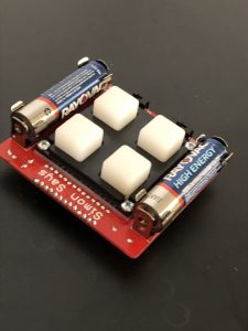
The Simon Says Project including the buttons, the batteries and the on and off switches
Simon Says Game
