David A.

Hi! My name is David and I am a rising junior at Ramaz Upper School. For my starter project, I chose to make a voice changer. For my intensive project, I decided to make a  car with a robotic claw attached to it which I can control with gestures I make with my hand. I chose this project because I wanted to really challenge myself in a variety of fields of engineering, including computer science, mechanical engineering, and electrical engineering.

Bluestamp really solidified my plan to go into electronics, as it really showed me how much I enjoy this field. I do not need to waste any time now- I know where I’m heading, and what my passion is. Until now, although I knew I wanted to go into a job involving math and science, I wasn’t sure whether it would be engineering, business, research, etc. Thanks to Bluestamp, I now know I want to go into technology, including all the engineering fields mentioned above. Furthermore, Bluestamp taught me how to be independent- although the nstructors helped out, they kept the help to a bare minimum. There were times where I felt stressed and annoyed, and I had to work at my problems and solve them, until it eventually paid off. I now feel like I can do anything by myself, as long as I put my mind to it.

Engineer

David A.

Area of Interest

Electrical Engineering

School

Ramaz Upper School

Grade

Rising Junior

Final Project

My final milestone was completing my project by building the claw and configuring its servos, as well as adding in the necessary code for the servos to work. First, I took out all the parts that came with the claw and organized them, before starting to build the claw according to the manual. I then proceeded to wire all the servos correctly into my circuit, and declare them as servos in my code. A challenge I ran into was that I had to change a lot of my circuit, since I had to power all the servos with 5 volts while the power for the rest of my circuit was 12 volts. Although I theoretically could have used the 5 volt pin on my Arduino, it was not actually working because its 5 volt regulator was overheating. Therefore, I had to install my own 5 Volt regulator, and then also add in a heat sink, so as to get rid of as much excess heat as possible. Next, I added the necessary code to power my servos, the bulk of which were if statements. On one Arduino, there was code that would send information depending on how I bent my fingers, while the other Arduino would carry out actions depending on what information it received.

Documentation

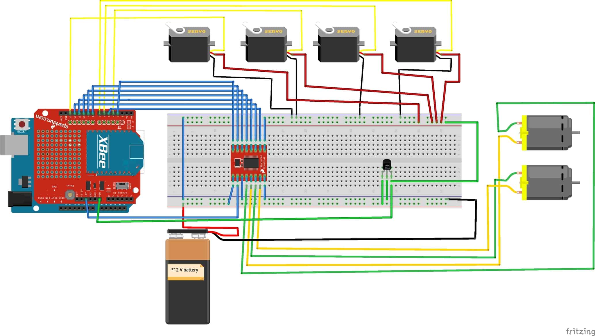
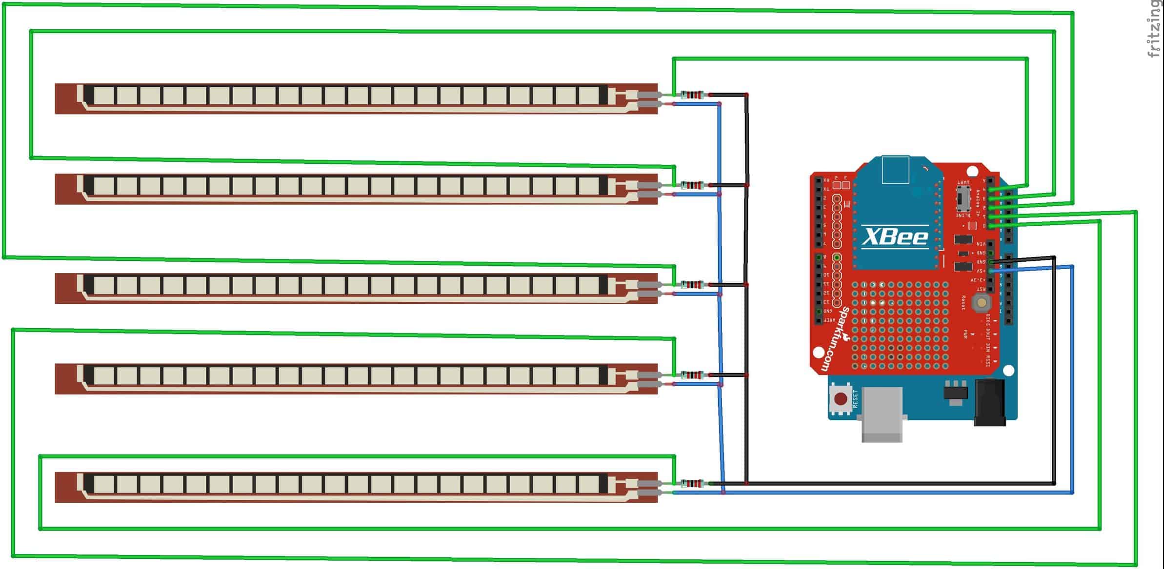
All my code can be viewed at https://github.com/adlerd2001/gesture_controlled_robot_code. This includes the code for my glove as well as the code for my robot.

Second Milestone

My second milestone was setting up my chassis and get it connected to my glove. To do so, I first had to configure the two XBees to communicate using the XCTU application. This was a real challenge for me, since I had to learn all of the different specifications that I could change on the XBees to make them unique and make sure no one else’s XBees interfered with my own. After I got them communicating, I made the necessary hookups between the XBees and XBee shields before attaching the shields to my Arduinos. There were so many necessary connections on my car that I also had to use a breadboard as well. I had to draw power from the 12-Volt battery pack to power three things- my Arduino, my motor driver, and my motors. To do so, I connected the battery to the Arduino, made a connection between the motor driver and the 5-Volt pin on the Arduino, and drew power from the “VIN” pin on the Arduino for my motors. I ran the power for the motors through a voltage regulator, since they can only handle 5 Volts, while the current going through the VIN pin was still 12 Volts, as it still didn’t pass through the built-in voltage regulator on the Arduino.  After I made all the connections, I created the structure for my project by sewing my flex sensors to my glove and using zip ties and hot glue to get the battery, Arduino, and the breadboard on my car. I also had to screw the wheels on. The next step was to write the necessary code to make the system actually work. I made code for the glove with several if-statements that basically said that if I do specific gestures, then the XBee would send specific characters to the other XBee. The XBee on the car had similar code, which contained if-statements which told it to do certain things based on what characters it received.

First Milestone

My first milestone was soldering all the flex sensors and getting them to work correctly. To do so, I soldered three wires and one 22 kilo ohm resistor to each flex sensor- one wire to the sensor’s “ground” pin and two wires and the resistor to the “Vcc” pin. The power supply gives electricity to the Vcc pin, and from there the current flows to the ground pin, causing the current to flow through the flex sensor. To the Vcc, I attached one wire to supply the sensor with power, but I soldered a resistor between the wire and the pin so as not to overflow the sensor with too much power. I attached another wire to the Vcc pin which connects to the analog reader on the Arduino, so that I can see what the current flowing through the sensor is at that time. The wire attached to ground connects it to the GND pin in the Arduino, hence completing the circuit. The flex sensors work by changing the voltage running through them. Bending the sensors add resistance in order to reduce the current running through them, which ultimately reduces the voltage. This change in voltage is read by the Arduino’s analog reader, which then displays this new value in the serial monitor. When the sensors are fully straight, they will read 100, and when fully bent, will read 0. Ultimately, I will use these sensors in my project by putting them on my glove, and programming code which says, for example, “if the value for sensor 1 falls below 50, then move the car forward”.

Starter Project

My starter project is a voice changer kit that I had to solder together. In the project, there was a variety of components which had to come together to act as a singular unit. It has some resistors which make sure that the system doesn’t “overflow” with energy, which would cause it to short-circuit. It also has capacitors which smooth out the current, thus allowing the voltage to remain the same. This ultimately puts less stress on the system, since there is less of a change in voltage. There are two integrated circuits (ICs)- one controlling the buttons to change the pitch/mode of the voice and the mic sensitivity, and another controlling the microphone, speakers, and volume change. The device is turned on and off with a switch, and I know when it is on/off because there is an LED that turns on when the device is on.

Leave a Comment

Start typing and press Enter to search

Bluestamp Engineering