
Hi, my name is Daniel and I’m going to be a rising senior at Leigh High school. I built a portable phone charger that uses solar power, power from a dynamo crank, and more. I am interested in electrical engineering, and this seemed like a good project to learn about electronics.
Solar Powered iPhone(5s) Charger Milestone #3:
Daniel V – Final Milestone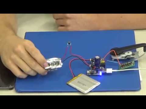
My final milestone was to use a a dynamo crank to charge the lithium-ion battery. I acquired the crank from an iRonsnow radio/flashlight, however I built the AC – DC converter circuit. The crank is a 3 phase AC power source, which means it has three power outputs. It has three power outputs because there is three separate copper coils that surround a magnet. When the magnet is spun, a electromagnetic difference(aka voltage) is created between the magnet and the copper coils.

In order to charge the battery I needed to convert the alternating current(AC) to direct current(DC). Even though AC current is more efficient, (less power loss), the solar charging circuit is DC, and so is the battery. I used 6 Schottky barrier rectifiers to ensure that power flows in the right direction and not too much power will be sent to the board.

Solar Powered iPhone(5s) Charger Milestone #2:
Daniel V – Milestone #2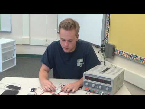
My second goal for this project was to design a circuit that could show how much charge the battery has. Originally I wanted to use an LCD display that would display the percentage of charge in the circuit, however that would require an extra microchip or microcontroller which would draw too much power. So it isn’t efficient to add a LCD display.
I ended up using RGB diodes to indicate charge’ because they don’t draw that much power, and because I wouldn’t have to program a microchip. RGB LEDs are actually three separate LEDs in one plastic case with a universal ground. I used a couple of resistors to make sure the LEDs changed color at the right points and a button, so the circuit would only draw power when the button is pressed. I attached the circuit to the LOAD output on my main charging board. The microchip on the charging board regulates the batteries power output based on how much charge it has. Based off those values I can determine how charged the battery is.

When the battery is at max charge, it outputs around 4.2 volts, and 2.5 when it has very little charge. Because current takes the path of least resistance, and because the red diode has the least resistance, the red LED is on when there is low power in the circuit. However at higher power the other LEDs are brighter and the red isn’t visible.

Solar Powered iPhone(5s) Charger Milestone #1:
The first objective of this project was to get the solar panel to charge the battery, and the battery to charge my phone. The solar panel inputs power into the battery and the battery output is then regulated to be constant. The battery power goes into the converter board which boost the current by 500mAh and Bucks the voltage to 5 volts making it USB compatible.

The way it works is the solar panel inputs approximately 4.5-5.8 volts and 560mAh (about 3 watts of power) into the the solar powered charging circuit. The microchip in the solar charger circuit optimizes the power input from the solar panel into the battery. The battery power is regulated by the microchip to be constant and then the power goes through the power boosting board. The power boosting board has a USB port, causing it to be able to charge the iPhone.

The next step is to add a battery charge indicator LED that will change color based on the current charge of the battery. I am also planning to implement a crank generator in my circuit to charge the my current battery, or to charge another battery.
TV-Be-Gone Starter project:

The TV-Be-Gone project is able to turn off almost any TV, because it uses infrared(IR) LEDs that interfere with the TV’s infrared waves it uses to transmit information. Infrared waves are undetectable by the human eye, and are commonly used to communicate information. Much like how a remote transmit IR waves to the TV to change the channel or volume, the TV-Be-Gone uses IR LEDs to send a sequence of IR waves or codes to the TV. The TV-Be-Gone is programmed to cycle through a series of TV codes, with the most popular ones first, and the least popular ones last. The IR LEDs blink at frequencies that the TV uses.
This circuit transmits IR signals by pulsing the 4 IR LEDs. The code for these sequences is stored in the ATTINY85V-10-PU microchip. The circuit cycles through the codes with the 8.00 MHz ceramic oscillator which acts as a clock for the circuit ensuring that the LEDs pulse at the correct times. The microchip outputs the sequences through 10kohm resistor R1 and to transistor Q5 which accelerates the current. Q5 then outputs to transistors Q1-4 which direct the right amount of current through each LED. The button is set to the reset function of the microchip, causing it to reset the sequence of codes. The green LED pulses each time a code is sent, and R5 is used to lower voltage through it.
https://learn.adafruit.com/tv-b-gone-kit/design-notes
https://learn.sparkfun.com/tutorials/ir-communication