
Hi my name is Clayton, I am a rising senior at The Bay School of San Francisco. My starter project is the Minty Boost, and my intensive project is the RC Robot Tank that can be controlled wirelessly using a PS2 controller.
Reflection
Coming into this camp I expected the six weeks to go by a lot slower than they did. I never would have imagined that I would learn so much and have so much fun doing it. I came into this camp with little programming and a lot of building experience. My goal for this camp was to become a better programmer and have a deeper understanding of what everything means when programming. Before coming to this camp I have built many robots for my robotics class and have always left the coding to another person. After this camp I feel confident in my coding skills to the point where I no longer need to rely on someone else to code for me.
Throughout the camp, we had many guest speakers come and speak about all the cool and interesting things they do and projects they work on. They also shared helpful tips and tricks on how to follow your passions in engineering. I still haven’t narrowed down what specific field of engineering that I want to pursue, I enjoy doing all of them. In this camp I was able to experience working in all the different types of engineering.
Modifications


Transmitter Code
// transmitter.pde
//
// Simple example of how to use VirtualWire to transmit messages
// Implements a simplex (one-way) transmitter with an TX-C1 module
//
// See VirtualWire.h for detailed API docs
// Author: Mike McCauley ([email protected])
// Copyright (C) 2008 Mike McCauley
// $Id: transmitter.pde,v 1.3 2009/03/30 00:07:24 mikem Exp $
#include
#include
#include
#include “utility/Adafruit_MS_PWMServoDriver.h”
#include
// Create the motor shield object with the default I2C address
Adafruit_MotorShield AFMS = Adafruit_MotorShield();
// Or, create it with a different I2C address (say for stacking)
// Adafruit_MotorShield AFMS = Adafruit_MotorShield(0x61);
// Select which ‘port’ M1, M2, M3 or M4. In this case, M1
Adafruit_DCMotor *leftmotor = AFMS.getMotor(1);
// You can also make another motor on port M2
Adafruit_DCMotor *rightmotor = AFMS.getMotor(2);
void setup()
{
Serial.begin(9600); // Debugging only
Serial.println(“setup”);
// Initialise the IO and ISR
vw_set_ptt_inverted(true); // Required for DR3100
vw_setup(2000); // Bits per sec
vw_set_tx_pin(1);
}
void loop()
{
char *msg = “1”;
digitalWrite(13, HIGH); // Flash a light to show transmitting
// vw_send((uint8_t *)msg, strlen(msg));
// vw_wait_tx(); // Wait until the whole message is gone
digitalWrite(13, LOW);
int button = Esplora.readButton(SWITCH_DOWN);
if(button == LOW)
{
char *msg1 = “2”; // Will show up as 50 on monitor on the reciever
vw_send((uint8_t *)msg1, strlen(msg1));
vw_wait_tx(); // Wait until the whole message is gone
}
button = Esplora.readButton(SWITCH_UP);
if(button == LOW)
{
char *msg2 = “3”; //show up as 51 on the reciever
vw_send((uint8_t *)msg2, strlen(msg2));
vw_wait_tx(); // Wait until the whole message is gone
}
else {
Esplora.writeRed(0);
}
button = Esplora.readButton(SWITCH_LEFT);
if(button == LOW)
{
char *msg3 = “4”; //show up as 52 on the reciever
vw_send((uint8_t *)msg3, strlen(msg3));
vw_wait_tx(); // Wait until the whole message is gone
}
else {
Esplora.writeRed(0);
}
button = Esplora.readButton(SWITCH_RIGHT);
if(button == LOW)
{
char *msg4 = “5”; //show up as 53 on the reciever
vw_send((uint8_t *)msg4, strlen(msg4));
vw_wait_tx(); // Wait until the whole message is gone
}
else {
Esplora.writeRed(0);
}
if(Esplora.readButton(SWITCH_LEFT) && Esplora.readButton(SWITCH_RIGHT) && Esplora.readButton(SWITCH_DOWN) && Esplora.readButton(SWITCH_UP))
{
char *msg5 = “6”; //show up as 54 on the reciever
vw_send((uint8_t *)msg5, strlen(msg5));
vw_wait_tx(); // Wait until the whole message is gone
}
}
Receiver Code
// receiver.pde
//
// Simple example of how to use VirtualWire to receive messages
// Implements a simplex (one-way) receiver with an Rx-B1 module
//
// See VirtualWire.h for detailed API docs
// Author: Mike McCauley ([email protected])
// Copyright (C) 2008 Mike McCauley
// $Id: receiver.pde,v 1.3 2009/03/30 00:07:24 mikem Exp $
#include
#include
#include
#include <utility/Adafruit_MS_PWMServoDriver.h>
// Create the motor shield object with the default I2C address
Adafruit_MotorShield AFMS = Adafruit_MotorShield();
// Or, create it with a different I2C address (say for stacking)
// Adafruit_MotorShield AFMS = Adafruit_MotorShield(0x61);
// Select which ‘port’ M1, M2, M3 or M4. In this case, M1
Adafruit_DCMotor *leftmotor = AFMS.getMotor(1);
// You can also make another motor on port M2
Adafruit_DCMotor *rightmotor = AFMS.getMotor(2);
void setup()
{
Serial.begin(9600); // Debugging only
Serial.println(“setup”);
AFMS.begin();
// Initialise the IO and ISR
vw_set_ptt_inverted(true); // Required for DR3100
vw_setup(2000); // Bits per sec
vw_set_rx_pin(4);
vw_rx_start(); // Start the receiver PLL running
}
void loop()
{
uint8_t buf[VW_MAX_MESSAGE_LEN];
uint8_t buflen = VW_MAX_MESSAGE_LEN;
if (vw_get_message(buf, &buflen)) // Non-blocking
{
int i;
digitalWrite(13, true); // Flash a light to show received good message
// Message with a good checksum received, dump it.
if(buf[0] == 50) // switch down
{
Serial.println(“down pressed”);
leftmotor->run(FORWARD);
leftmotor->setSpeed(255);
rightmotor->run(FORWARD);
rightmotor->setSpeed(255);
}
else if(buf[0] == 51) // switch up
{
Serial.println(“up pressed”);
leftmotor->run(BACKWARD);
leftmotor->setSpeed(255);
rightmotor->run(BACKWARD);
rightmotor->setSpeed(255);
}
else if(buf[0] == 52) //switch left
{
Serial.println(“left pressed”);
leftmotor->run(FORWARD);
leftmotor->setSpeed(255);
rightmotor->run(BACKWARD);
rightmotor->setSpeed(255);
}
else if(buf[0] == 53) // switch right
{
Serial.println(“right pressed”);
rightmotor->run(FORWARD);
rightmotor->setSpeed(255);
leftmotor->run(BACKWARD);
leftmotor->setSpeed(255);
}
Serial.print(“Got: “);
for (i = 0; i < buflen; i++) { Serial.print(buf[i], DEC); Serial.print(” “); } Serial.println(“”); digitalWrite(13, false); } else if(buf[0] == 54)// if no buttons are pressed the motors will stop running { rightmotor->run(RELEASE);
leftmotor->run(RELEASE);
}
}
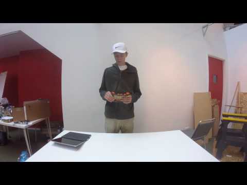
When I finished the building of my tank and it was time for me to start on the modifications. I knew that I wanted to attached a camera on my tank and if I wanted to put camera, I would need the tank to have a lot more range than its current 32 feet. So the second modification of my tank would be the extending the wireless range of my tank. To extend the range of my tank i ordered a nRF24 transceiver which we could not get to work so then we ordered the RF transmitter and receiver which would expand the range up to 500ft. To make sure that the transmitters worked I connected them to separate arduinos and having the transmitter send over numbers and having the receiver recognizing those numbers and turning them into text. This took some time to figure out because a lot of the code wasn’t working and when it started to work, the header pins on With the new transmitter and receiver, I also ordered the Arduino Esplora controller. It took sometime and some research to figure out how to connect the transmitter to the Esplora controller. Once I figured that out, I started to assign variables to different buttons and when they are pressed, the transmitter would recognize it and send numbers. When the receiver would receive those numbers, it would turn them into text that would say which button was pressed. Then instead of it just printing out numbers when a button was pressed, I turned them into movements. Once I was able to control the tank smoothly, I attached the camera onto the tank. The camera is the Fat Shark Teleporter, now I can see where my tank is going without seeing my tank.
My Second Milestone
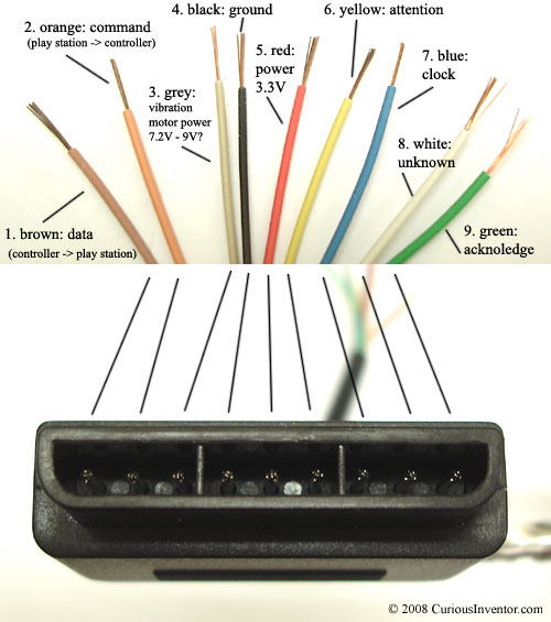
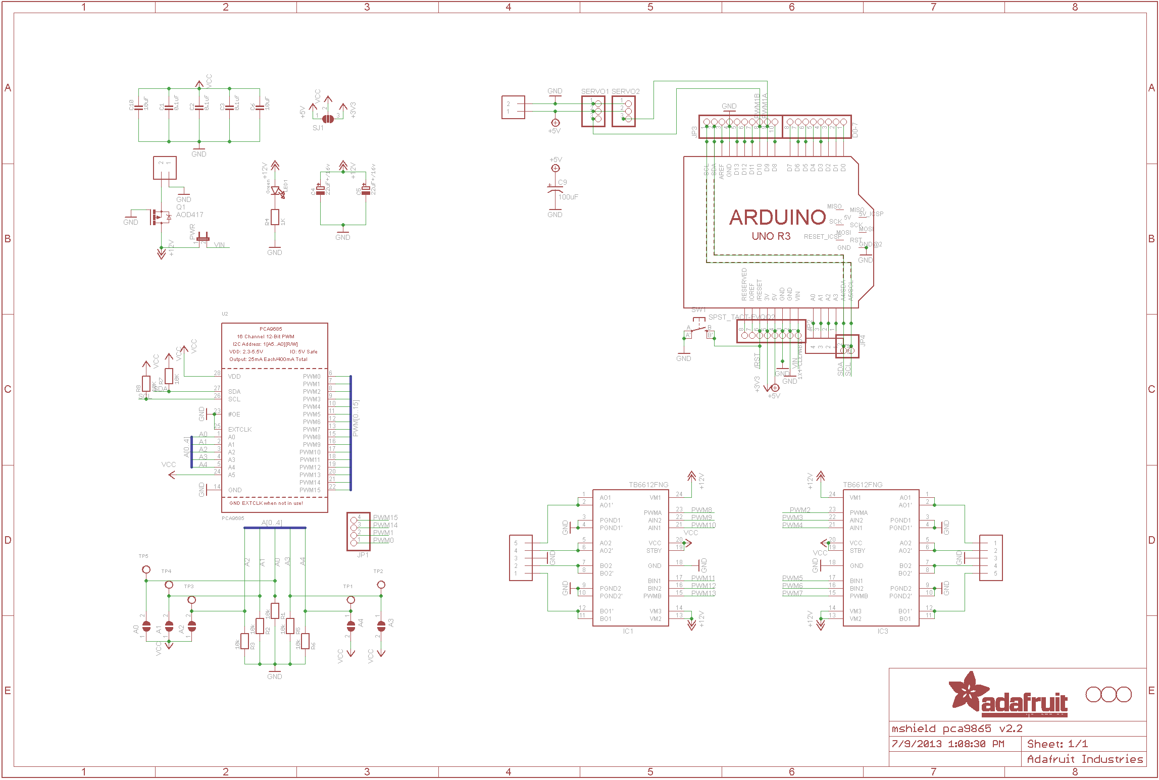
Today is June 27, 2016. I have now finished my second milestone of my main project. My main project is the Remote Controlled Robot Tank. Today I have completed combining the Adafruit motor shield v2.3 to the Arduino Uno board, wiring of both boards, connecting the dongle, and coding the tank to move. Connecting the motor shield to the Arduino board was hard at first because I had no clue how to do it until I asked a peer and they helped me out. Once I learned how to do it, it was very easy. I connected the header pins and soldered them in place. Then I attached it to the Arduino board. After that, I began wiring the now combined motor shield and Arduino board to the PS2 dongle. That took some time to complete that because I had to make sure that everything was correctly color coded and in the right ports. Once everything was connected and wired, I plugged it in to make sure the wireless controller was able to connect to the dongle. Coding the tank to move was the hard part because I spent most of the time thinking that there was something wrong with the code. I researched how to troubleshoot it and nothing came up, so after a while of just sitting there out of ideas, I asked if an instructor if they could help me. We figured out that I forgot to put the male header pins into the SCL and the SDA. Once I place them in and re uploaded the code, the tank started to move. Now that it was moving, I was able to program what buttons do what. I programmed the forward on the right track to R2 and backward on the right track to R1. On the left track I programmed the forward to L2 and the backward to L1. Now the tank is running smoothly.

My First Milestone
Today is June 21, 2016, I reached my first milestone of my main project. My main project is the Remote Controlled Robot Tank. Today I started and completed the build of my tank which included the building of the gear box, chassis, treads of the tank, and attaching the gearbox to the chassis. When building the gearbox, I set the gear ratio 58:1 because I wanted the tank to be fast. The hard part of building the gearbox was getting the gears to stay in place without falling out. When building the chassis of the tank, it was fairly simple because I used the Tamiya track and wheel set so I was able to complete that quickly and efficiently. When attaching the gearbox to the chassis of the tank, I ran across the trouble of screwing it in because the screws that came with the universal plate were not working. So I had to find other screws that worked. Once those where found, it was pretty easy to put everything together, and I finished it quickly. When building the treads of the tanks, there where three different sizes of tread that I could put together. The directions told me that I can attach them any way I want. When I completed the fist tread and started on the second, it became apparent that I needed either one long piece or two small pieces to complete it. I had to find the correct pattern of long, medium, and short pieces to connect together to complete the track.
Starter Project: Minty Boost
My starter project was the minty boost. The Minty Boost is a portable charger that can charge any device that plugs into a USB to charge. The circuitry is housed in a Altoids tin. The minty boost is powered by two AA batteries which will charge your phone for hours.
On the Minty Boost circuit board the R5 resistor is a 3.3k which is used to improve the high current capability of the boost converter chip. Next is the R2 and R4 75K resistors, which determines what type of charge is being connected to the system. Next, you have the C1 and C2 capacitors. The C1 capacitor is non polarized so it can go either way. The C1 will help to stabilize the output voltage and any unwanted high frequency noise, making sure the 5V output is running smoothly. The C2 capacitor stabilizes the the boost converter chip to allow it to generate a voltage as precise as possible. Then the D1 diode is part of the boost converter but it is used to make sure the energy of the circuit is flowing in one direction from the batteries to the USB port. The IC socket which is placed over the R5 resistor and is used to hold the chip will allow you to replace the chip if anything happens to it. The power inductor, L1, is used to convert low voltage into high voltage. On the inside of the inductor is just a coil of wire that has no polarity, and the flow of electricity can flow both ways. There are two electrolytic capacitors which help smooth both the input and output voltages. The electrolytic capacitors are polarized so electricity can only flow one way through it. The circuit is then connected to two AA batteries. The two AA batteries only supply three out of the five volts needed to charge a device. So the three volts go through the boost converter chip which turns those three volts into the needed five volts.
Some of the challenges that I faced included mixing up the resistors. The resistors were so close in color, and only a couple of the colored bands were different, that I got confused multiple times and soldered them in the wrong spots. After I realized my mistake it took me a solid 45 minutes to try and get them out. That took much of my building time away from me.
Something that I learned from this project was that it is important to go slow, make sure everything is in the correct place, and even if you’re one hundred percent sure it is in the right place, go back and double check anyways. Sometimes it’s better to be slow and make little to no mistakes, than to be fast and always having to go back and fix something you messed up on.