
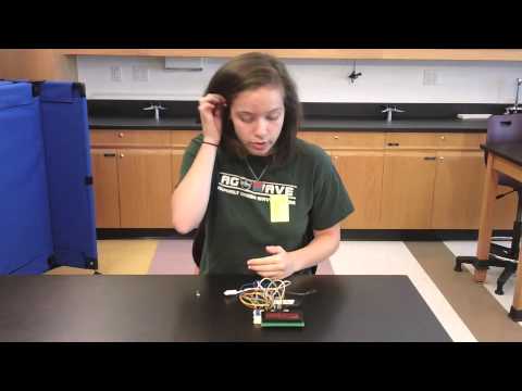
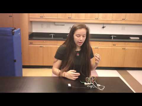
My name is Callie, and I’m going to be a junior at Dalton in the fall. Over these past few weeks I created a bike speedometer. I chose this project because I wanted to come out of the program with a project that I would use, so I could really be proud of all the work I’ve put it. Additionally, I figured my bike, which is actually my mom’s from her college days, could use a few modern touches.
While I came into the program with some coding knowledge because I’ve taken two years of computer science at school, I came in with little to no prior knowledge of anything electrical. Even so, because of the code-heavy nature of my project, most of the challenges I faced were in coding aspects of my bike speedometer. By overcoming these issues, I feel that I’ve become more proficient in coding. At school I code in Java, but my project has to be coded in Arduino, so I learned about the different features of either language. Perhaps more importantly, I learned strategies for how to code. Many times during the course of my project, I felt overwhelmed because I felt like nothing was working. I learned that identifying the problem is the first step to fixing it.
My starter project was a light organ, which displays light as the microphone picks up music, or any other sound. It was through this project that I increased my proficiency in electrical matters. However, going forward, I would really like to learn more about electrical and mechanical engineering.
Bike Speedometer
 |
|
Final Milestone

My final milestone is putting everything onto my bike. I attached the door sensor to the bike frame using a U-clamp and the magnet to the wheel. The latter provided some challenges because the reflector light on the wheel came off, so I had to put it back on before I could attach the magnet to it.
I used the dremel to cut a square in the top of my project box for the LCD screen. I also drilled holes in the bottom of the box so the wires from the sensor could come into the box and so I could reach the on/off switch. I attached the box to my handlebars using two more U-clamps.
I had one big challenge this milestone. When I finally attached everything and was ready for it to work, nothing happened. After extensive troubleshooting and then finally going back to my original wiring tutorial, I realized that some two wires had ended up in the wrong place, and thus there was no data going to the Arduino. I’m really proud of this milestone because it means by bike speedometer is fully done!
Schematic:

My Code: Speedometer_Code
Final Bill of Materials: Final Bill of Materials
Second Milestone
I’ve gotten to my second milestone! I have coded my bike speedometer for what seems like forever, but I’ve come out on top. I have learned how to print on an LCD display, created a way to calculate the average and current MPH, fixed the code that was creating a very insensitive sensor, created a timer, implemented a pause option, and continued to expand my knowledge of Arduino syntax.
The first problem I encountered was how to make sense of the endless string of 0s and 1s that is my sensor data and create a MPH reading from that. When the magnet attached to the bike wheel passes by the sensor, the sensor reads ‘o’. The sensor reads ‘1’, however, when the bike wheel is turning and the magnet is away from the sensor. This data continues to come in as long as the program is running, so I wanted to create an infinite array of the sensor values; unfortunately, Arduino does not have this capability, so I had to find another option. I tried using a boolean that was connected to the sensor, but that did not help make sense of the data.
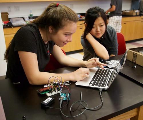
Then I discovered the millis() function, which, when called, returns the number of milliseconds it has been since the program restarted. To get the average rotation time of the wheel, I divided the current millis by the total number of turns. I then did calculations to get an average MPH reading from the average turn time. I was not satisfied with this, however, because it was not a current MPH reading. Below is a picture of an instructor and me working on the average MPH calculation.
I had a hard time trying to get a current MPH reading. I originally wanted to find a way to make my average turn time variable more recent, perhaps by resetting it every minute or valuing data from the last minute over previous data. I found a way to run a function every minute, but I struggled to figure out what to put inside.
Ultimately, to get a current MPH value, I record the timestamp, in millis, of the last time the magnet passed by the sensor in a variable named ‘lastPass’. The next time the magnet passes the sensor, I subtract the millis of the last pass from the millis of the current pass to get the rotation time, in milliseconds. When I divide the wheel circumference (mine is 86.4 inches, or 2.4 yards) by the rotation time and do unit conversions, I get the current MPH. During testing, I was getting a current MPH reading that was spiking and dropping drastically. To get a more stable reading, I report current MPH after every ten turns.
At my last milestone, I had used a delay of 500 milliseconds at the beginning of each loop so I would not be getting constant data values. After lots of testing, I realized that this was contributing very greatly to the lack of sensitivity of the magnet because even if the magnet passed by the sensor, the sensor would not pick it up if it was during the delay. This was a very important step in my coding because I identified the problem. I was getting very frustrated because I was having big issues, without knowing why. When I identified the issue, I was then able to address and ultimately fix it. When I got rid of the delay, however, the sensor was picking up values so fast that it would read one pass of the magnet as up to ten turns, resulting in MPH values that were off the charts!
To remedy this problem, I created the boolean ‘passing’. When the magnet is away from the sensor, when the wheeling is turning, I set passing to ‘false’. When the magnet is passing by the sensor, I set the boolean to ‘true’. Only when passing is false and the sensor value is 0, does the Arduino go through the pass calculations, which are increasing the number of turns and calculating current MPH. This means that a sensor value reading like ‘1100000000111’ is treated like ‘110111’.
I have created a timer, also using the millis() function, to record how long a biker has been riding. Similarly to how I use lastPass, I also have a ‘lastTake’ variable. If it has been 1000 milliseconds or more (just in case) since the last take, I increase seconds by one and set lastTake to millis(). I continue to do this, and eventually, when seconds gets up to 60, I set seconds to 0 and increment minutes up by one. This works the same way for a minutes to hours conversion.
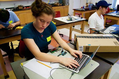
Creating a timer took a long time for me because I was looking in the depths of the Arduino Playground, the help section of Arduino, looking for libraries and code that would help create a timer. I tried downloading timer libraries, using modulo, and creating an elapsed time variable, all of which did not work. With the help of an instructor, I finally realized that using millis() and incrementing seconds, minutes, and hours was a much easier way to make a timer. A valuable lesson I learned through this experience was that taking a step back can help a lot. Additionally, writing what I want my code to do on paper and in plain English helps me get ideas out. Then, I can translate that into code. The picture below shows me doing the aforementioned method of work.
Something I was especially eager to do was implement an internal pause option, and I was very happy when I succeeded in doing so! My program constantly checks to see if it has been 10,000 milliseconds, or 10 seconds, since the last pass of the wheel. If it has been, the program enters the pause statement. In that if statement there is a while loop that the program is kept in until the sensor receives a value of 0. Only then can the program un-pause.
During my work leading up to this milestone, one of the less conceptually challenging things I learned, though no less important, was intricacies of Arduino syntax. I learned that defining one’s variables correctly is very important. There were many times where I would be getting ostensibly random, bizzare values and didn’t know why. Only after a lot of debugging did I realize that it was because I had declared something as an int, and integer, instead of a float. Ints cannot actually hold that much information, and when its value becomes too large, the int wraps around and becomes negative. When I assigned millis() to an int, at around 30 seconds the int would be too big and cause the calculation to sit at .07 and not change. Now any variable I need for calculations is declared as a float because they can hold more data and can have decimals. Sometimes when using floats, I was not adding .0 to the end of numbers that they were interacting it, causing the floats to round when I did not want them to. Additionally, I was getting a weird string of 1 values whenever my Arduino was starting up. Arduino has a hard time starting up, so I added a 1 second delay in the set up loop to remedy this issue.
I’m very proud of all the coding I’ve done for this milestone and I think I’ve learned a lot. I am excited to put all the circuitry into a project box and connect everything to my bike!
First Milestone
I have reached my first milestone! All parts of my project have been connected. I connected the battery to the Arduino, which is the brain of my project, and then the Arduino to the LED display, which allowed me to light up its backlight. Next, I connected the potentiometer to the LED display, which allows me to adjust the contrast of the writing. The potentiometer is a resistor with rotating contact, so it resists the current more or less according to how the knob is turned. I used this tutorial for the wiring of my LCD screen.
A big challenge for me was figuring out how to connect my reed sensor to the Arduino and then be able to get information from it. Ultimately I connected one wire of the sensor to a digital pin on the Arduino and the other to ground, which allows the reed sensor and Arduino to communicate. My reed sensor is an “always open” read sensor; its default is open, which does not let current pass through the circuit. When a magnet passes the sensor, the circuit closes. Once the magnet moves away, the circuit opens again. Because my sensor is an “always open” sensor, I programmed the digital pin to be an INPUT_PULLUP pin. Setting the pin to simply INPUT would have allowed the Arduino to get information from the sensor, but would have given faulty values when the sensor was open. An alternative to programming the pin as INPUT_PULLUP would be to use an external resistor. However, using the pin in this way takes advantage of the Arduino’s built in pull-up resistor. This means that when the sensor is open, the resistor connects to 5 volts of energy, which leads the Arduino to report “1” or HIGH. In comparison, when the sensor is closed, the pin is pulled to ground, 0 volts, causing the Arduino to report “0” or LOW. I use the 0 or 1 report method and have the Arduino report the status of the switch every 1000 milliseconds, or 1 second.
I have coded the Arduino on my computer, and thus can print whatever I want onto the Arduino from my computer. However, my circuit also works without the computer since I have uploaded my code to the Arduino microcontroller. The reed sensor can send information to the Arduino, which displays it on the LED display.
Starter Project
My starter project is a light organ, which is used to produce a light display when music is played. Parts include LEDs, light-emitting diodes, the lights in the display; resistors, which slow down electrical current so the current doesn’t overheat; trimmer resistors, which adjust sensitivity of the microphone or speed of LEDs; and capacitors, which store energy in an electrical field, measured in farads, microfarads, or picofarads; and those described below.
The light organ begins working when the microphone picks up music and the transistors amplify the signal so that the IC, which stands for integrated circuit, chips can use it. When IC1, the smaller one, gets the amplified signal, it turns on and proceeds to oscillate signal to pin 3, which connects to IC2, the larger. IC2 has one of its pins connected to the central yellow LED, so when that pin gets a pulse signal, that LED lights up. When IC2 receives a pulse at pin 14, it shifts the current to another of its pins. These pulses are sent through four transistors in a sequence. When a signal passes through a transistor, the 6 LEDs it is connected to light up. The power for the whole light organ comes from a 9 volt battery.
The biggest problem I encountered in this project was when I initially soldered 24 of 25 LEDs in the wrong way, meaning that I placed the anode where the cathode should have been. This happened because I did not follow the diagram correctly; instead I reversed its orientation in my head. When I found out this error, I was very frustrated, but I set to desoldering all the LEDs and re-soldering them in the correct way, at the cost of a few burns on my hand from the soldering iron. Another issue I had during this project was when I tried to strip the wires attached to my microphone, but ended accidentally cutting them, leaving me with almost no wire to work with. Additionally, the wires came off my microphone a few times, so I had to solder them back on.
Though this project took longer than I expected, I am very glad with my end product. I also feel that I learned a lot during my production of the light organ. I learned that I might need to take more care and double check my work rather than trying to rush through it. I also learned that when something doesn’t go my way, I need to bounce back and set my mind towards fixing the problem. Initially, looking at the parts list for this project, I understood about 20% of the words; now I have a working definition of pretty much the whole list.
Dear Callie
Your frustrations were cutting wires while stripping and burning yourself while soldering. 59 years ago I built an ECCO 100 watt stereo receiver and a Heathkit receiver took all summer but I learned to solder and strip and have used those skills for ever.
You solved the science part with facility and that is the fun part isn’t it?
Makes me jealous that I can not be with you to discuss your work as you solve the problems since as you know I can’t program a VCR or transfer a call on my cell phone. Build what ever kit there is now so you get the BLUE COLLAR SKILLS you need in a WHITE COLLAR WORLD.
Love you Callie and are very proud of you.
Grand daddy and Nana.
Great Callie, lots to learn, now you can talk engineering with me, not that stopped you anyway….Enjoy!
We are so very proud of you
It seems your blip was cutting wires while stripping and burns with the soldering iron
59 years ago I built an ECCO 100 wat stereo amplifier and HEATHKIT receiver took all summer
but learned to identify resisters, capicitors etc and stripped and soldered 1000 wires
build something and learn the BLUE COLLAR SKILLS you need in a WHITE COLLAR WORLD
we love you Cal
grand daddy and Nana
I cannot even begin to comment on the science and engineering of this project .. just too overwheming. What I do undertstand is the lifelong value in your having learned to take more time, rather than rushing through a situation. You now recognize when soemthing does not go your way, you can bounce back and set your mind to solving the problem. I, now, do not even know the meaning of 20% of the words, but you have expalined your project so thoroughly that that I clearly understand the concept. I trust this project has given you the pride in yourself as it has given me such pride in you.