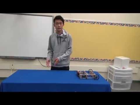
My name is Bill, I am a rising sophomore at Leland High School. For my starter project, I did the minty boost phone charger, and my main project is the self balancing robot.
Before coming to Bluestamp Engineering, my knowledge on engineering and coding were almost nonexistent. I am a three week student, and I have learned a lot over the course of this program, but not by reading a book, or from lectures. I learned about engineering while building my project and experiencing roadblocks that I must solve. Bluestamp is not a class, it’s the real life application. I think that’s why I enjoyed it. When I chose a project, I aimed for something that I knew would be challenging, that would be able to push my limits and knowledge. I am proud of what I have been able to accomplish during my time here. The most challenging aspect of my project is that I did not have any documentation for my specific prototype. People have created self balancing robots, but they used different parts, and their code was not compatible with mine. I wrote most of my code, and learn how to do it along the way. There Even though my self balancing robot is not perfect, it was my best effort with the knowledge that I had. Engineering is an interesting field to study. After Bluestamp, I think my curiosity for engineering had been rekindled.

Final Milestone
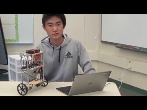
For my final milestone, I fixed my code to allow the robot to correct itself once it started drifting towards one direction, and I talk about ideas and plans for future modifications.
BOM – My bill of materials
Code – All the code I worked with in Bluestamp
Sources – Websites that helped me out
Complementary Filter – A guide onthe complementary filter
Electrical Component Schematics

To work on the balancing, I figured out how to accelerate the speed of the motors over time, when there was a constant angle. The code is not perfect, but it works in that the balance is almost, if not already autonomous. There are still various aspects of the coding of this robot that I am not familiar with and still need to learn.
For my modifications that I plan, I definitely want to perfect the code still. I will need help from someone much more skilled than me at coding in the future to do that. I think that the option for myself to control it’s forward and backward movements is a modification I can work on in the near future. I understand how to use xbees to allow a controller to wirelessly communicate to my self balancing robot, it shouldn’t be too difficult to control the movement of the robot. By adding a forward and backward feature, I can also manually stabilize the robot with the controller. Another modification that I would like to add, although smaller, is to add LED’s to indicated the status of the robot. For example, stabilizing, forward, or backward. I can’t make the robot turn unless I replace the current motor driver, because half of it is broken. Right now, I am sending one signal to both motors, so it is able to balance fine, and move in 2 directions.
Third Milestone
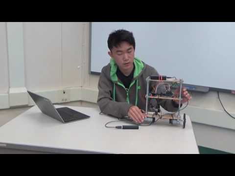
My third milestone consists of more stabilizing of the robot during balance, so that it’s position does not oscillate. In my next milestone, I will perfect the balance system.
Stabilizing the Robot
At the end of my second milestone, I managed to make the robot balance for a few seconds at most. I decided to change values, and edit the complementary filter. I could not manage to make the robot accelerate it’s speed over time from my lack of coding knowledge. That part may be something I will do in the future once I have more coding skills. I did a of trial and error testing, and finally got a result that was much better than my second milestone. The main problem with my robot right now is that the IMU is not always calibrated right. When the robot is in it’s balancing position, I may get a reading of 2 degrees, when I needed a reading of 0. A lot of micro positioning work had to be done to adjust the angle of the IMU on my robot, so that it was properly calibrated with my robot’s balance position.
In my second milestone, I stated that there were problems with the robots oscillating, or not having enough power. I made several if, then statements to fix this. The main problem was that sometimes if there was a small angle change, the motors would not have enough power to reverse the tilt. Once the angle increased, the motor’s power increased too much, and tilted it past the balance point. By using if, then statements, I was able to adjust the motor’s speed for certain ranges of angles. For example if the angle was between 1 and -1 degrees, the motor speed would be 15*angle, but if the angle was between 1 and 3, and -1 and -3, the motor speed would be 11*angle. This way, I could target at which angle the robot was having issues, and adjust speed values.
Second Milestone
My second milestone consisted of making the robot able to balance on its own. Much easier said than done. I ran into many problems and barriers. Balancing is not perfect, but it is as close as I can get.
Almost Balanced
I had a problem in my past documentation with balancing, which I explained earlier. It was how when a tilted robot is countered at a constant speed, the robot will eventually fall over. The way to fix this is by constantly increasing the speed over time, so that the robot will not fall over. I wrote some code to do this. If the PWM was positive, every loop would increase the value by a little, and if the PWM was negative, every loop of the code would decrease the value by a little. This way, the speed accelerated over time, even if the angle was the same. The robot seems to “balance” much better. I think I am making a lot of progress at this stage, and my milestone 2 is almost finished.
Applying a filter.
As I stated in my previous documentation, the gyro values tend to drift over time. The accelerometer readings do not drift, but they start out very noisy. We use the short term gyro readings, and then combine that with the accelerometer readings, in the complementary filter. The equation looks like this:

By taking 98% of the gyro readings and 2% of the accelerometer data, this integrates both the gyro and accel values, and makes sure that the measurements do not drift over time.
Balance attempts and Problems
I found a library online which allowed me to get the values from my IMU, and show them on screen. After completing the first milestone, making the robot balance is the hard part. I found a piece of code that I use as a template for my self balancing robot. Essentially, if I input a positive value as the torque variable, the code would make the motors spin forward, and if I input a negative value, the motors would spin backwards. In theory, this way, the tilt would be countered with a motor pushing it back to upright position.
My first attempt at balancing was to use the raw angles I obtained from the IMU, the angle that correlated with the tilt of the robot. I multiplied this angle by a number X, set that as the PWM value, and then put it into the loop of code. The number X represented how powerful the motors would spin when getting angles. I ran into many problems while trying to calibrate the balance. First of all, the angle was a raw gyro value, and the gyro values can drift over time. This is why I implemented a complementary filter later on. When testing the balance with this mehod, I ended up with two results. In the first scenario, the robot would start tilting, but the motors did not counter the tilt with enough torque, so the robot would fall over. In the second scenario, there would be too much motor torque. Because of this, the motors would counter the tilt, but too much so that it would then tilt the other way, and that caused the robot to oscillate violently until it fell over. At this point in time, the motor speed was directly proportional to the angle of the tilt. This would not work. The problem is that when there is a tilt, and it is being countered with a constant speed, the robot will eventually tip over.

First Milestone
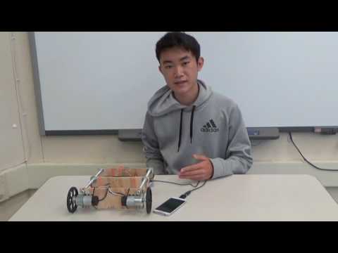
My first milestone consisted of building the chassis, connecting all the electronic parts, and putting everything together to make sure the robot was ready to balance. I ran some code to turn the motors forward and backwards in a loop, while also getting angles from the gyroscope, to indicate all components were working.
The Process
Working on building the self balancing robot introduced me to arduino, and other components that work with it. To familiarize myself, my first task was to make an LED light blink using arduino. Connecting all the components required me to search for product schematics online, and understand what every wire connects to. When I had the IMU installed, I needed to get the readings from it. I found a library online that included code to get the readings, and turn them into degrees, etc.
The motor driver has two pins for direction, two pins for power, and a PWM pin. PWM (Pulse width modification), is a type of digital signal. In the case of my motor, it represents the speed of my motor. Now the construction was complete, all my components were working, and I was ready to make the robot balance.
I ran into my first problem while working on my first milestone. I attempted to connect my motor to the motor driver and arduino, but it did not work. I tried resoldering my capacitors, the motor and 9V battery were working, LED’s on motor driver were working. No current was present where the motor should have received power. I connected my motor to the motor driver, and the motor driver to the arduino. I plugged in all the necessary wires and ran a code that supposedly spun the motor forward and backward. There was no power going to the motors. I checked all the connections and they were fine. It turns out that there was a bad soldering at the motor connection, and I quickly fixed it. The motor is now working fine.
Starter Project
For my starter project, I worked on the mintyboost phone charger. It used the power of two AA batteries to charge a phone at 0.5 Amps. AA batteries themselves do not have the voltage to charge a phone, being only 3V in total. By using an inductor, the voltage was able to be stored, and increased to 5V. Aside from being a useful project, it introduced me to the fundamentals of soldering, and basic knowledge of the components of an electrical circuit. I learned the functions of resistors, capacitors, diodes, transistors, etc.

Starter Project Video