3D Printed Robotic Hand

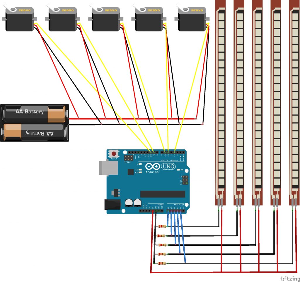
This 3D Printed Robotic Hand bends its fingers accordingly to your movements while wearing a glove with flex sensors. The flex sensors are variable resistors and are attached to one side of a voltage divider. The other side has resistors of a constant value. The Arduino uses the change in voltage when the flex sensors are bent and then triggers the servos to move a proportional amount. The servos pull strings that act like tendons in a hand, allowing the fingers to move.

Engineer

Austin P.

Areas of Interest

Computer Science, Engineering

School

Mission San Jose High School

Grade

Rising Sophomore

Schematic

DIY 3D Printed Robotic Hand Schematic

Useful Links

Reflection/Showcase Video

Throughout my 6 weeks at Bluestamp Engineering, I have learned a great deal in both engineering and coding. I have been taught how to troubleshoot and solve problems by myself. At this summer program, I felt more independent since we were informed by the instructors that they would not provide answers to the students questions unless we have tried three different ways to try to solve the problem. I think that Bluestamp’s way of teaching is very unique and promotes students to grasp the art of troubleshooting and solving problems by themselves and I feel that I have mastered this skill.

I discovered that both the software and engineering aspects of my project were extremely fun and enjoyable to do. I feel that through my experience at this program, I would like to major in either computer science, or a category of engineering. Overall, the Bluestamp Engineering summer program has been a great experience and that I have learned a great deal through my 6 weeks here.

Milestone 3

My third milestone includes my modification which is making my robotic arm respond to inputs in the serial monitor. When I press the number 1 key, the hand would gesture, showing the number 1 and I did this for the numbers 1 through 5.

Although this modification seems simple, I spent some time trying to figure out how the Arduino can understand my keyboard inputs. In the end, I found out that you could use serial.read to give you the first byte of incoming serial data available. I took the incoming byte to make every keyboard input unique and then was able to code so that each key from 1-5 gave a different gesture on the 3D printed robotic hand.

Milestone 2

My second milestone was sewing all five flex sensors onto the glove and mounting the 5 servos onto the 3D printed robotic hand. Currently, only 4 of the flex sensors control the 5 fingers of the 3D printed robotic hand. There is only enough space to fit 4 servos in the hand, and therefore only 4 servos are currently mounted. After the mounting process, I proceeded to calibrating the servos to figure out how much they actually need to turn to make the fingers bend to their maximum possible position. I did this for each servo since every finger has a different amount that it needs to bend. After that, I calibrated the flex sensors since no flex sensor is perfect and each may send a different signal to the Arduino’s analog pin when at similar positions. After calibration, my 3D printed robotic hand project has been completed.

However, during my journey from milestone 1 to milestone 2, I faced many problems. The main problem I encountered was that the servos and servo horns did not fit comfortably into the space provided in the 3D printed robotic hand. The servos were a little bit taller and did not fit all the way down in the space provided in the 3D printed hand. The servo horns of each servo were too long and would collide with each other because the servos were mounted adjacent to each other. To solve this problem I was trained in using the dremel and used the tool to trim off the edges of each servo horn. Another difficulty I had was that some of my servos would burn out and stop working. The problem was caused by the higher than normal amount of voltage provided by the 7.2V battery. It provided over 8V to the servos when fully charged while the servo only required between 4.8V to 6V to run. I resolved this problem by using a buck converter to step down the voltage from the input(battery), to the output(servos).

Milestone 1

My first milestone was getting the servos to rotate accordingly to how much the flex sensors were bent. At this point the circuits for the flex sensors and the servos have been properly assembled. I have also written code so that servos turn corresponding to the flex sensors.

This all works through the use of a voltage divider in the circuit. There is a variable resistor, the flex sensor, and resistors of static value, the 22k ohm resistors. Through Ohm’s law, V=IR, if current(I) stays constant and resistance(R) is increasing when the flex sensor is bent, voltage(V) must go up. Because of this, the voltage drop at the resistor must increase. This results in less voltage that is being detected by the analog pins of the Arduino. Arduino is able to sense the change in resistance through the change in voltage it detects. This allows the Arduino to calculate how much the flex sensor is bent, enabling it to be able to tell how many degrees the servo should turn.

Some problems I encountered included making sure my circuit was assembled properly following the schematic. I also struggled while writing code so that the servos turned proportionally with how much the flex sensors were bent.

Starter Project

The Big Time Watch is a watch that uses a 4-digit LED display screen in order to tell you the time.


Important Parts:

  • 7-segment display x1
  • 32kHz crystal oscillator x1
  • microcontroller (ATmega328) x1
  • 0.1μF capacitors x2
  • 10k ohm resistor x1
  • battery holder x1
  • coin cell battery 5V x1

There is a 7-segment display that is powered by the coin cell battery, displaying numbers through the use of 7 segments in order to tell time. The 32kHz crystal oscillator oscillates, allowing the microcontroller to properly time 60 seconds. The two 0.1 μF capacitors are use to store energy with an electric field. This electric field is formed by two oppositely charged plates. The area between the plates is known as the dielectric. The dielectric is an insulating material and its purpose of the dielectric is prevent the two plates from making contact. Then we have the 10k resistor. This resistor is used to reduce the current flow of electricity.

Leave a Comment

Start typing and press Enter to search

Bluestamp Engineering