
Hi!
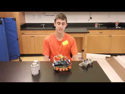
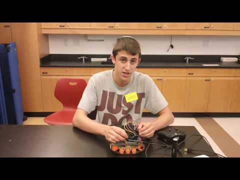
asdfI’m Ari and I am a rising senior at SAR High School. My starter project is the Minty Boost, a portable phone charger powered by AA batteries. It uses an inductor and a boost converter chip to increase the voltage from 3 volts to 5 volts. My main project is the R/C Tank, a vehicle with treads that moves based on commands given from a wireless PlayStation 2 controller. The project is based in large part on Paul Blesich’s and I consulted some other BlueStamp students’ portfolios for assistance. In the future, I want to continue to pursue engineering but I’m undecided on what branch.


Here is my Bill of Materials
Here is my Build Plan
Here is a Zip file with my latest tank code with the ultrasonic sensors: RCTankCodeAriIwithultrazip
Here is a Zip file with the code for my tank, ultrasonic sensors, and NeoPixels: RCTankCodeAriIwithneozip
Here is a Zip file with the tank code without the ultrasonic sensors: RCTankCodeAriIzip
Here are the libraries I used: Adafruit Motor Shield Library, PS2X Library, HC-SR04 Ultrasonic Sensor Library, Adafruit NeoPixel Library
Final Video
asdfFor my final video, I changed a few things. Firstly, the 4 battery pack wasn’t cutting it for the 6 volt motors so I got a 7.4 volt LIPO battery to power the tank. I also changed the way the tank receives power. The battery connects to a switch which connects to the external power block on the motor shield. Then, I have a jumper wire from the positive (+) power block to the VIN slot, feeding power to the Arduino. Lastly, I added two ultrasonic sensors: on the front and on the back of the tank. These sensors give off a signal that bounces back when it hits something. The sensor can determine how far away an object is by the amount of time it takes for the signal to return. If an object is within 10 cm of the tank, it travels forward or backward automatically. Also, if there is an object on both sides of the tank, it rotates 90 degrees so it can then move forward.
Here is an updated schematic with the ultrasonic sensors (a more clean and simple version can be found under Second Milestone Video):

Second Milestone Video
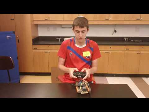
asdfFor my second milestone, I accomplished a few things. First, I powered the whole tank through one battery. I did this by connecting a portable charger into the USB B of the Arduino and using a VIN Jumper to connect the two boards. I didn’t do this earlier because the manual for the Motor Shield says not to (pages 23-24). However, after every other way to power the tank with one battery failed, I tried it and it worked flawlessly. Next, I attached all the different parts to the tank’s body so it would be fully mobile. After this, I wanted to be able to move the tank at different speeds instead of only at full speed. For this I used the joysticks. The joysticks are mapped in an X,Y axis (due to the fact that the motors only move forward and backward, I ignored the x values and only focused on the up/down of the y-axis) from 0 on the top to 255 on the bottom. I split the axis into three parts. If the Y value was less than 125 (above the middle), the motor would move forward. With this section, I used the map function in Arduino to map the values so that the higher the joystick was, the faster the motors would move. The second section stated that if the Y value was more than 130 (below the middle), the motor would move backward and I mapped those values as well. Finally, if the joystick was between 125 and 130, the motor would be released and the tank could be controlled by the buttons’ functions.
asdfAfter the video was filmed, we received better motors and I took apart the chassis to put them in. However, these motors were 6 volt motors and my battery pack was 5 volts. I then took a 4 AA battery pack, connected it both to the USB and to the external power block on the Motor Shield, and removed the jumper. I did this because the USB regulates the power to be only 5 volts and the motors needed more.

First Milestone Video
asdfThis is the RC Tank, my main project. I started to build this by assembling and connecting the three parts of the chassis: The gearbox, the universal plate, and the tracks. The instructions for this were not great but using multiple drawings and some past projects, I built the tank’s body. I chose a 114.7:1 gear ratio in order to balance out torque and speed. Next, I moved on to the Arduino Uno and Adafruit Motor Shield V2.3. I soldered pins in to connect the two boards and I downloaded the Motor Shield library. After that, I learned about Arduino and how it worked by using the DC motor example and converting it to work with my two motors. Next, I took the PS2 receiver, found what each of the pins do, and downloaded the PS2 library from Bill Porter. I connected the pins accordingly to the Motor Shield (and Arduino) and tested the PS2 example code. Then, I modified Paul Blesich’s code to work with my Motor Shield and motors. At this point, I am using two portable chargers to power the Arduino and Motor Shield respectively (into USB B and External Power Block) because I had issues when only using one supply.
Starter Project Video
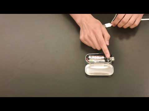
asdfThis is the MintyBoost Phone charger. It takes the power of two AA batteries and puts it through an inductor. Because it is simply a coil of wire, when the current flows through the inductor, a magnetic field is created. Then, the boost converter chip flips a switch to create an alternate circuit for the current to run through, thereby lowering the current in the inductor. With a change in current in the loop, a magnetic field is created. Additionally, through the law P=IV, when the current goes down, the voltage rises. Then, because of this change of voltage, the inductor creates an opposing and equal force to keep itself stable. This opposing force travels through a one way diode and out into the USB port. I thought it was a very cool starter project and I learned a lot!

Adafruit MintyBoost Schematic