
Hi! My name is Anke, a rising sophomore at Homestead High School. In my free time, I play piano and do TaeKwonDo. My starter project was a Voice Changer from Apogee Kits, and its tutorial can be found here. My main project was a modified version of an indoor hydroponic farm, which has its main tutorial here.
Reflection:
I now know more about DIY (Do It Yourself). Most of my parts came in 10′ sections, and I had to use a hacksaw to saw them for my own modified project. My instructor encouraged me to use alternatives instead of buying hanger hooks and PEX crimpers just for a small amount of crimping and four downspouts. As a result, I grew much more resourceful, and I was able to put most parts together by myself. By the end of my two weeks, I was able to work without trying to consult my instructors every ten minutes about what I should do. I improved my research skills drastically, as I found resources on Arduino forums and paid close attention to different instructables for my own project. Some websites had more pictures, but were missing the schematics for the electronics and several key steps to the building. I combined the good parts and compiled my own build plan for my modified project here. I would have improved/added several things if I had more time: 1) the commenting for the project’s code, as the original author of the code made it pretty hard to follow, 2) the leaks in the structure, with better glue such as two-part epoxy, 3) more parts for the electronics, with a two-channel relay module board that would actually turn the 5 volts from the Arduino to 12 volts for the solenoid valve, and shut off water circulation, and perhaps the pH and nutrient control that was included in the original project. However, overall I am satisfied with the condition of my project considering the amount of time I spent on it, and what I’ve learned from it.
Resources:
The schematics I based my project off of are here.
My BOM (Bill of Materials) is here.
My own build plan is located here.
The code for the water float sensors is here. Uncomment all the code for more functions, such as more pump, temperature, pH, and nutrient control.
Milestone #3
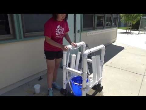
For this milestone, I completed the entire system for water circulation. The pump is attached to the side of the bucket with suction cups, with PEX pipes leading outside and up to the drip emitters, which then drip the water down the downspouts into the gutter, and everything returns to the bucket through a vinyl hose. There are the float sensors in the bucket, and when they sense that the water is low, an orange LED light flashes on. There are three main leaks, one in the return vinyl hose and two at the PEX endcaps. However, I ran out of epoxy glue and had to improvise with a combination of cement solvent acrylic and hot glue, which is not entirely waterproof, so I only managed to slow down the dripping rate and not stop it entirely. It’s been a great two weeks and I love how my project came together at the end!
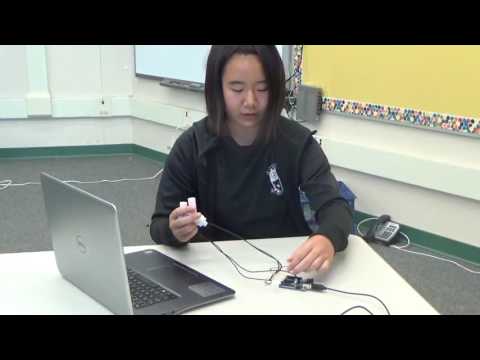
The third milestone is for the electronics portion of the project. I have two float sensors, one lower in the bucket, and one higher in the bucket. Their purpose is to measure the amount of water in the water storage tank(bucket). They have a small empty space in their heads, as well as magnets, so that when they are mounted and in water, the heads rise up and thus disconnect the two magnets inside, and break the circuit. The code in the Arduino recognizes that when at least one float sensor’s circuit is disconnected (when at least one head is still floating in water) that the water bucket doesn’t need refilling. When both sensors’ circuits are unbroken (both heads are not suspended by water anymore), an LED connected to ground(GND) and a resistor, which leads to pin 13, lights up with an orange glow, warning that the bucket needs to be refilled. Unfortunately, my 2 channel relay module did not work, so I am unable to generate enough voltage for my solenoid valve to be able to turn the water flow on and off. Therefore, the pump has to be turned on and off manually, and it won’t stop pumping when water is low. However, I gained knowledge about how the system would work if the solenoid valve could function, as well as a much clearer understanding of the Arduino parts.
This is a schematic of an Arduino with a working relay module. What I did was only connect the two float sensors, one at pin 7 and ground (the sensor on the lower part of the bucket) and one at pin 8 and ground (the sensor near the top of the bucket). I inserted one leg of a resistor (anything up to 1K ohms should work) in pin 13, and wrapped its other leg around the positive long leg of the LED. The shorter negative leg of the LED is inserted into ground.

Milestone #2

For the second milestone of the hydroponic farm, I installed PEX tubing and the vinyl hose parts for water transportation and water return, respectively. I don’t have an actual water storage tank yet, but I borrowed a small plastic basket for this video. The water will travel up the thin white PEX tubing from the storage tank up to the two separate branches, where there are four total drip emitters for the water to come down into the downspouts, and into the gutter. There are holes on the sides of the two gutters that face inward, and two male 1″-3/4″ barbed adapters on the outside of the gutter threaded into a female 3/4″ PVC connectors in the inside of the gutter. Two 6″ vinyl hose parts each attach to one of the 1″-3/4″ barbed adapters, and are joined together in the middle by a 1″ barbed tee. A third 6″ hose part is attached to the third leg of the tee and leads into the plastic box. With the plastic box, I would have to cut a 1″ hole in it, thread a 1″-3/4″ barbed reducer through it, and attach the third 6″ hose part to it, which constitutes the water return.
Here is the general picture of the structure with PEX pipes.


Milestone #1
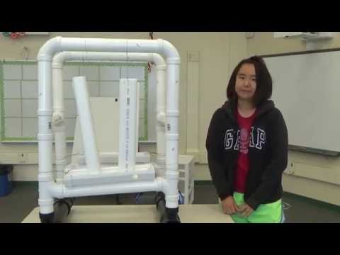
My main project is a hydroponic farm, which is a vertical farm that has the ability to water the plants with pH and temperature adjusted water. This milestone was for completing the basic framework for the farm, with 2″ PVC pipes acting as most of the supporting frame and 3″ PVC pipes as the base. The downspouts are 1.5′ PVC 2″x 3″ downspouts, hung on the top two PVC pipes from wires, and they empty into a 16″ PVC gutter. The structure is the same on both sides of the farm. Water will flow down the downspouts and collect in the gutter, and empty out through a hole in the side back to a storage tank of water. As I don’t have much time at BlueStamp, I altered some aspects of the farm to make the project easier to do in two weeks of full-day participation. First of all the framework is sized down from ten feet tall to approximately two feet tall, and with four downspouts instead of twenty. Additionally, because this project is merely a prototype to complete the water circulation aspect of the hydroponic farm and I won’t grow any plants in this structure, I didn’t make holes in the downspouts to hold plants. I plan to install the PEX pipes next, which will transport water from a storage tank up to the top of the downspouts.
These are the schematics for my supporting frame:
Main Leg: Top frame: Bottom frame:
:


Starter Project
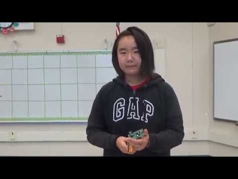
Hi! I’m Anke, a rising sophomore at Homestead High School. This is an electronic voice changer. The main parts of this starter project are the two chips and the vertical and horizontal trimmers, as well as the four buttons that control the voice output types. There is the vibrato voice, the high-pitched voice, the low-pitched voice, and the robotic voice. You speak into a microphone soldered onto the board, and the different types of voices are output through a speaker connected to the board. The large chip is called the HT8950A, and it changes the frequency of the input voice into the four output voices mentioned above. The smaller chip is the LM386N, which is a low voltage audio power amplifier. The horizontal trimmer adjusts the sensitivity of the microphone, and the vertical trimmer adjusts the volume of the speaker. I learned how to solder and a little bit about circuits while doing this starter project.