
Roomba
For my first year over at Bluestamp Engineering, I created a Roomba that picks up dust and powder from the ground while also avoiding crashes with any object in its way due to the ultrasonic sensor in the front to detect obstacles/walls in the way. I chose this project because I wanted to create a robot that can help people while not being a hassle to deal with and set up.
Engineer
Alejandro B
Area of Interest
Robotics and Computer Programming
School
KIPP NYC College Prep
Grade
Incoming Junior
Reflection
My time in Bluestamp was a unique experience because I was able to build a project from scratch without much help. This is the first program I’ve been to that does something like this and it has taught me many things that many other kids my age won’t know until they get to college. Going to this program during my summer has put me ahead and I’m grateful for it. All the programs I went to, including Bluestamp, will help me when getting into college and even a job because I’ll have an early start. More students should take this program if they have the time and money for it.
Modification
My modification for my Roomba is a vacuum cleaner that I created using a bottle, a motor, and a propeller. The vacuum cleaner works but the vacuum it creates isn’t powerful enough to suck anything. The way I want to fix that however is to get a stronger motor and create a better propeller. (video link of video I followed: https://www.youtube.com/watch?v=eZMeeZvEC_c)

Final Milestone
My Roomba is able to clean small things such as dust, powder, and sawdust with a shoe brush and a lint roller. Using the obstacle-avoidance aspect of my Roomba, it can go around by itself cleaning and not get stuck. The lint roller in the front picks up dust, fur, powder, and sawdust until it is full of particles and can not stick anymore. The shoe brush behind the lint roller moves the particles forward that the lint roller missed and then when it backs up, the lint roller will pick it up.

An issue that I encountered was that the lint roller was positioned in a way that made it so the wheels were not touching the ground so the Roomba could not move. The way I fixed it was to remove the roller and glue it back a bit higher off the ground. Another issue with the lint roller was that it was too sticky so the motors moving the wheels could not turn, move forward or backward because it was not stronger than the stickiness of the lint roller on smooth surfaces. I couldn’t fix that issue so it only moves on surfaces that are not smooth enough for the lint roller to stick to easily such as wood floors or tables. What I learned from this entire project is that tasks that seem simple are not simple or just take longer than expected. Also, there are many steps and issues in a project that can make the project take a long time to finish, especially if those issues are hardware issues. For my future projects, hopefully I can be quicker and able to create more difficult projects. When I first started this project I only had some coding experience with Java and Python and a general idea of how to build a Roomba. Now I know how a motor driver works, how to use Arduino IDE, code commands onto an Arduino, how to solder, and how to use a breadboard to connect wires without soldering. Now that my Roomba is finished, for additions I want to create a mini vacuum cleaner and hopefully 3D print a cover to hide the inside of the Roomba and make it look cool.
Second Milestone


My Roomba now will move forward until it encounters an object/wall. When it reaches a wall it will then back up and turn right about 45 degrees. The ultrasonic sensor in the front of the Roomba is sending high frequency waves which bounce back when they encounter an obstacle. The receiver then uses that input and sends it to the Arduino which then relays that information to the motors to either go forward or back up and turn right based on the code I wrote for the Arduino.
Here is a diagram of the process the Roomba goes through when turned on.
Here is a diagram of how an ultrasonic sensor works.

Also, at some point I took the Roomba apart and placed the parts back through nuts and bolts rather than tape. I also used zip tie to carry the 6v battery on the bottom so it stops falling and soldered the wires connecting from the motor driver to the motors. The least straightforward component of this milestone was programming the sensor to detect objects and move accordingly. So I decided to choose a link and edit it with some help and after two days of searching, I made it work. For the future, I will just choose one set of code online and edit it or create one from scratch to save time and not take a long time creating the right code. Now I just need to attach the cleaning parts to my Roomba, which might prove challenging but I will make it work.
//Libraries

#include "Ultrasonic.h"


//Constants

const int EnA = 10;

const int motorA1= 7;      //motor A positive (+) pin to pin 7 (PWM) (from L298 module!)

const int motorA2= 6;     //motor A negative (-) pin to pin 6 (PWM)

const int EnB = 5;

const int motorB1= 8;     //motor B positive (+) pin to pin 8 (PWM)

const int motorB2= 9;     //motor B negative (-) pin to pin 9 (PWM)


Ultrasonic ultrasonic(A4 ,A5);       //Create Ultrasonic object ultrasonic(trig pin,echo pin)


//Variables

int trigPin = 11;       // Trigger

int echoPin = 12;    // Echo

long duration, cm, inches;

8

void forward() {

digitalWrite(motorA1, HIGH);        // Function for moving forward

digitalWrite(motorA2, LOW);

analogWrite(EnA, 225);

digitalWrite(motorB1, HIGH);

digitalWrite(motorB2, LOW);

analogWrite(EnB, 255);

}

void backward(){

digitalWrite(motorA1, LOW);    // Function for moving back

digitalWrite(motorA2, HIGH);

analogWrite(EnA, 225);

digitalWrite(motorB1, LOW);

digitalWrite(motorB2, HIGH);

analogWrite(EnB, 255);

delay(1000);

}

void left() {

digitalWrite(motorA1, HIGH);        // Function for turning left

digitalWrite(motorA2, LOW);

analogWrite(EnA, 225);

digitalWrite(motorB1, LOW);

digitalWrite(motorB2, HIGH);

analogWrite(EnB, 255);

delay(200);

}

void right() {

digitalWrite(motorA1, LOW);    // Function for turning right

digitalWrite(motorA2, HIGH);

analogWrite(EnA, 225);

digitalWrite(motorB1, HIGH);

digitalWrite(motorB2, LOW);

analogWrite(EnB, 255);

delay(200);

}

void stop() {

digitalWrite(motorA1, LOW);    // Function for stopping

digitalWrite(motorA2, LOW);

digitalWrite(motorB1, LOW);

digitalWrite(motorB2, LOW);

}


void setup() {

pinMode(motorA1,OUTPUT);

pinMode(motorA2,OUTPUT);

pinMode(motorB1,OUTPUT);

pinMode(motorB2,OUTPUT);

pinMode(trigPin, OUTPUT);

pinMode(echoPin, INPUT);

}


void loop() {

// The sensor is triggered by a HIGH pulse of 10 or more microseconds.

// Give a short LOW pulse beforehand to ensure a clean HIGH pulse:

digitalWrite(trigPin, LOW);

delayMicroseconds(5);

digitalWrite(trigPin, HIGH);

delayMicroseconds(10);

digitalWrite(trigPin, LOW);


// Read the signal from the sensor: a HIGH pulse whose

// duration is the time (in microseconds) from the sending

// of the ping to the reception of its echo off of an object.

pinMode(echoPin, INPUT);

duration = pulseIn(echoPin, HIGH);


// Convert the time into a distance

cm = (duration/2) / 29.1;     // Divide by 29.1 or multiply by 0.0343


if (cm > 15){            // If and else if statements for the Roomba to detect objects

forward();            // or walls and move accordingly

}

else if (cm <= 15){

backward();

right();

}

}
First Milestone

My first milestone was to connect the Arduino to the motors to get the wheels to spin. After that and a bit of coding later, I am able to make the Roomba move forward, left, right, and backward. It has a motor, wheels, Arduino, L298N motor driver, 6v battery pack, portable charger, and a chassis. The way the L298N motor driver works is through a H-bridge electrical circuit, which is a circuit that switches the polarity of a voltage applied to a load. The Roomba moves as instructed so when I finish my second milestone, it will be able to continue moving forward until an obstacle is detected. Which then the Roomba will move back and turn.
H-bridge circuit diagram (Left)

Getting the Roomba to move wasn’t a straight forward process. The first issue I came across was that I did not have a single clue as to what an L298N motor driver was or how it works. So I used Google and learned that it uses the H-bridge concept, which I did not know how that worked either, so after a few searches I learned how the L298N and a H-bridge circuit worked. My second issue was that I had no idea how to connect the battery and Arduino to the L298N. But after another Google search, I found a video that showed me where to connect what wires with the exact slot. My last issue was that the Roomba turned left slightly when backing up, however that issue could be a good feature because when the Roomba is coming close to a wall, when it detects the wall and the Roomba backs up, it will already know to turn as it backs up. After these problems, I learned that when programming the directions on the motors, it takes a while to calibrate it to go straight when going forward, backward or turn exactly 90 degrees left or right. This was an interesting first milestone that is not too difficult but not too easy, the other milestones feel like they would take longer to accomplish so this is just the start of a long process to build a fully functional Roomba.
// connect motor controller pins to Arduino digital pins

// motor one

int EnA = 10;

int In1 = 9;

int In2 = 8;

// motor two

int EnB = 5;

int In3 = 7;

int In4 = 6;

void setup()

{

// All motor control pins are outputs

pinMode(EnA, OUTPUT);

pinMode(EnB, OUTPUT);

pinMode(In1, OUTPUT);

pinMode(In2, OUTPUT);

pinMode(In3, OUTPUT);

pinMode(In4, OUTPUT);

}

void goStraightLeftRightBack()   //run both motors in the same direction

{

// go Forward

// turn on motor A

digitalWrite(In1, HIGH);

digitalWrite(In2, LOW);

// set speed to 150 out 255

analogWrite(EnA, 255);

// turn on motor B

digitalWrite(In3, HIGH);

digitalWrite(In4, LOW);

// set speed to 150 out 255

analogWrite(EnB, 225);

delay(2000);

// now change motor directions

// go Backward

digitalWrite(In1, LOW);

digitalWrite(In2, HIGH);

digitalWrite(In3, LOW);

digitalWrite(In4, HIGH);

delay(2000);

// turn Left

digitalWrite(In1, HIGH);

digitalWrite(In2, LOW);

digitalWrite(In3, LOW);

digitalWrite(In4, HIGH);

delay(650);

// turn Right

delay(500);

digitalWrite(In1, LOW);

digitalWrite(In2, HIGH);

digitalWrite(In3, HIGH);

digitalWrite(In4, LOW);

delay(650);

// now turn off motors

digitalWrite(In1, LOW);

digitalWrite(In2, LOW);

digitalWrite(In3, LOW);

digitalWrite(In4, LOW);

}

void loop()

{

goStraightLeftRightBack();

delay(1000);

}
Starter Project
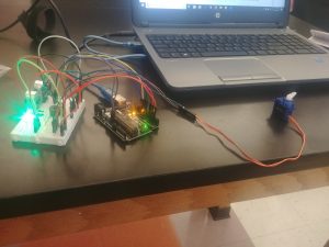
My Starter Project is a motion sensor using an Arduino. When the distance sensor detects movement within 10 inches, a buzzer will continuously beep, a red light emitting diode (LED) will turn on, and a servo motor will spin a peg 45 degrees left and right. If no movement is detected, then the green LED will stay on until turned off.
How it works
The motion sensor’s distance sensor’s transmitter (trig pin) sends a signal that when it comes in contact with an object, it will be reflected back to the receiver (echo pin). Then that input goes to the Arduino which then the Arduino will output that to the red LED, the piezo buzzer, and the servo motor. A light emitting diode is similar to a light bulb, once it receives enough electricity it will turn on. However, a diode is an electrical component with polarity, meaning that electricity can only flow in one direction; it will not work in the reverse direction. An LED has two terminals (anode and cathode) that when they are in the correct polarity, it will produce light.
#include <Servo.h>                // Include the servo library


const int trigPin = 11;           // Connects to the trigger pin on the distance sensor

const int echoPin = 12;           // Connects to the echo pin on the distance sensor


const int redPin = 3;             // Pin to control the red LED inside the RGB LED

const int greenPin = 5;           // Pin to control the green LED inside the RGB LED

const int bluePin = 6;            // Pin to control the blue LED inside the RGB LED


const int buzzerPin = 10;         // Pin that will drive the buzzer


float distance = 0;               // Stores the distance measured by the distance sensor


Servo myservo;                    // Create a servo object


void setup()

{

Serial.begin (9600);        // Set up a serial connection with the computer


pinMode(trigPin, OUTPUT);      // The trigger pin will output pulses of electricity

pinMode(echoPin, INPUT);        // The echo pin will measure the duration of pulses coming

// back from the distance sensor


// Set the RGB LED pins to output

pinMode(redPin, OUTPUT);

pinMode(greenPin, OUTPUT);

pinMode(bluePin, OUTPUT);


pinMode(buzzerPin, OUTPUT);       // Set the buzzer pin to output


myservo.attach(9);                // Use pin 9 to control the servo


}


void loop() {

distance = getDistance();           // Variable to store the distance measured by the sensor


Serial.print(distance);         // Print the distance that was measured

Serial.println(" in");              // Print units after the distance


if(distance <= 10){                         // If the object is close


// Make the RGB LED red

analogWrite(redPin, 255);

analogWrite(greenPin, 0);

analogWrite(bluePin, 0);


// This code wiggles the servo and beeps the buzzer

tone(buzzerPin, 272);         // Buzz the buzzer pin

myservo.write(45);            // Move the servo to 45 degrees

delay(100);                       // Wait 100 milliseconds


noTone(buzzerPin);            // Turn the buzzer off

myservo.write(135);           // Move the servo to 135 degrees

delay(100);                       // Wait 100 milliseconds


} else if(10 < distance && distance < 20){     // If the object is a medium distance


// Make the RGB LED yellow

analogWrite(redPin, 255);

analogWrite(greenPin, 50);

analogWrite(bluePin, 0);


} else{                                     // If the object is far away


// Make the RGB LED green

analogWrite(redPin, 0);

analogWrite(greenPin, 255);

analogWrite(bluePin, 0);

}


delay(50);      // Relay 50ms between each reading

}


//------------------FUNCTIONS-------------------------------


// RETURNS THE DISTANCE MEASURED BY THE HC-SR04 DISTANCE SENSOR

float getDistance()

{

float echoTime;                   // Variable to store the time it takes for a ping to bounce off an

// object

float calculatedDistance;         // Variable to store the distance calculated from the echo time


// Send out an ultrasonic pulse that's 10ms long

digitalWrite(trigPin, HIGH);

delayMicroseconds(10);

digitalWrite(trigPin, LOW);


echoTime = pulseIn(echoPin, HIGH);      // Use the pulsein command to see how long it

// takes for the

// pulse to bounce back to the sensor


calculatedDistance = echoTime / 148.0;  // Calculate the distance of the object that reflected the

// pulse (half the bounce time multiplied by the speed

// of sound)


return calculatedDistance;              // Send back the distance that was calculated

}
Motion Sensor Schematic
