Fully Automated Robotic Feeding Arm

An arm composed of 3 joints that uses edge to edge detection to sense and correspondingly pick up food to then feed it to an individual.

Engineer

Aditya B

Area of Interest

Electrical Engineering

School

Cupertino High School

Grade

Rising Freshman

Demo Night

Throughout these last 6 weeks my project took my turns and required much troubleshooting. The steps I perceived to be quick and simple turned out to be the most challenging such as creating the physical arm and also working with kinematic equations to control the motor movement. Through these challenges, I learned the physics behind arm movement and the importance in proper design while also becoming good with the Pi and object detection.

When looking at the future of my project, I would like to develop and use a higher accuracy object detection program while also incorporating voice detection. That way the arm can be controlled by simple voice commands.

But all in all this project brought out the best and worst it me. While facing a multitude of issues I ended up  learning a variety of systems and concepts I never thought I’d learn. While making this automated robotic arm, I found out I want to work on hardware and software projects and that I discovered a new interest in using software to optimize mechanics. By far Bluestamp was a fun time and a really interesting experience.

Final Milestone: Automated Arm Movement with Object Detection

img_4272

For my third and last milestone, I wanted to implement object detection using a raspberry pi camera to automate the feeding process. 

As you can see, there is a camera at the end of the arm and when the program begins, the arm moves to a predetermined location and takes a picture of the plate. The Pi then processes the image to identify how many objects there are and draws a rough border around the object and calculates the center. The program uses edge to edge detection. Edge detection is an image processing technique for finding the boundaries of objects within images. It works by detecting discontinuities in brightness. I was able to loop through the pixels and analyze the pixel using HSV which stands for Hue, Saturation, Value. Hue is the actual color, saturation is the intensity of color and and value is the lightness or darkness of the object. Using these 3 factors, the program can accurately detect the object and draw  lines on the edges. Once the object center is identified, the coordinates in the image are converted to polar coordinates, which the arm can then move to. 

In just this milestone, I was able to learn the in and outs of object detection, the forms of it and how to implement basic and advanced forms of object detection. I was able to explore advanced forms of object detection that implement machine learning. On the other hand I learned how to convert between regular cartesian coordinates to polar coordinates. 

I faced many struggles when trying to identify more than one object and objects with more than 4 sides. The original program only could work with one object and simply found the corner coordinates. When I wanted to implement the detection with more than one object, it required a real edge detection that analyzed the brightness between different pixels to detect edges instead of corners.

Now my arm is fully operational and can pickup the food, feed it to you and go back to pick up more food. I would like to add voice detection to control the arm. This help people are who are unable to eat to trigger the code by voice commands and choose which food on the plate they would like to eat.

Second Milestone: Arm Control using Inverse Kinematics

img_3679
2019-07-19-093122_1920x1080_scrot

 My second milestone was to get to build the actual arm and then program the  4 servos to work together using inverse kinematics to move to any set location on a plate. Here is a quick demo:

For the time being, I have created a grid on top of my plate to act as a way to identify a certain location and correspondingly move to it. The program requires an x coordinate or a column number and also a y-coordinate or a row number. As you can see the see, as soon as I input the coordinates, the arm lifts up to a set, standard location and then adjusts each of the motors and then begins to move down. Currently there are pencils in the place of the fork, which are used to measure the accuracy of the arm. After the arm goes down to pick the food, it moves up to a pre-assigned location, close to the users mouth.

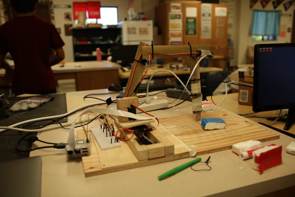
This milestone was heavily focused on constructing an arm that ensures the servos have enough torque to move the arm and up and down while also preserving the accuracy when moving to the center of a food piece. Over the course of the last few weeks, I have constructed a few designs and went through multiple iterations when figuring out the best, most minimalistic design to hold the servos in place. There are 4 servos moving in different directions, that allows the arm to reach a large radius and every possible spot on a plate placed in front of it. The first motor is on the very bottom, and rotates the entire structure in a 180 degree radius. The other 3 servo motors, move in the same axis but work together to move to a certain spot.

I used inverse kinematics to control the first 3 servos. Inverse kinematics is the use of kinematic equations to determine the parameters that provide a desired position for each of the robot’s end-effectors. So in order to achieve a certain location on the grid, the first 3 servos each need to move a certain amount.

Currently, the circuit is composed of servo motors and a raspberry pi. The wiring has not changed since my previous milestone. There are 4 servos each 3 pins each which need to be connected to ground, an external power source and a GPIO Pin on the Pi.  I used the generic GPIO pin code, I was able to use a for loop to move the motors back and forth. 

I faced many struggles when creating the arm. My first design was heavy, ineffective and unnecessarily large. I ended redoing the entire design while also adding multiple support to balance the weight of the arm.

Now that the structure of my arm is up and running and I can easily input the coordinates and the arm is able to move to it, the next step is to attach a camera and using opencv to detect the food and correspondingly move to it. 

First Milestone: Raspberry Pi Controlled Servos

1stmilestone_schematic.fzz_
img_3354

My first milestone was to get the 4 servos working with the Raspberry Pi. Here is a quick demo:

As you can see the see when the program begins, the 4 servos begin to move back and forth for 3 times before stopping. 

Currently, the circuit is composed of servo motors and a raspberry pi. The 4 servos have 3 pins each which need to be connected to ground, an external power source and a GPIO Pin on the Pi. A GPIO pin is a general purpose input output pin, that the raspberry pi has many of. On the software side, the Raspberry Pi is it’s own computer and uses the linux operating system which gives you a lot of freedom when choosing an IDE to work with. I went with the pre-downloaded application, Thonny python which simplified the uploading process. Using the generic GPIO pin code, I was able to use a for loop to move the motors back and forth. 

Originally, I had decided to use an Arduino to control the servos for my arm but the camera that would be used for food detection requires a more powerful operating system which the Raspberry Pi can satisfy. After setting up the Pi, I constantly tried to get the Arduino and Raspberry Pi to communicate but after a few days of failure, I tried to use the pins on the Pi itself to control the servos, which ended up working well. Through all these efforts I was able to learn the underworkings of the Raspberry Pi, its operating system and how it can communicate with other devices. I also learned how the rest of my project is going to turn out as I understand the python language used to communicate with the Pi.

I faced many struggles when transitioning from the arduino to the Raspberry Pi. They are 2 vastly different platforms and getting the servos to move on the Pi was much different then the Arduino and getting the devices to easily and smoothly communicate is tiring and can be inconclusive.

Now that I got my servo motors to work, the next step is to get the shape of the arm up and working. I will attach the servos to a series of wood pieces and design an arm to make sure any part of the plate can be reached. 

Starter Project: Motion Alarm

starterprojectschematic
starterproject

Hello, my name is Aditya and I am a rising Freshman at Cupertino High School. For my starter project, I decided to build the Motion Alarm. I chose it because it required both software and hardware and also had real world applicability. Here is a quick demo.

As you can see, the ultrasonic sensor is able to identify the distance of the object put in front of it and correspondingly lights up an RGB LED and turns on a buzzer. The ultrasonic sensor sends pulses and receives the echo to determine the distance of the object placed in front of it. Based on the distance, the alarm will light up a green light if there is no object near it, a yellow light if an object is near it and a red light along with a buzzer, when an object is pretty close to it.

The circuit required jumper wires to connect components, resistors to provide resistance to the electrical current in order to provide an appropriate amount of energy to the LED, an RGB LED that can create 16million colors and a buzzer to dictate the closeness of an object, an ultrasonic sensor to sense the distance of an object and lastly an arduino with a proto shield.

I learned how to use an RGB LED, an Ultrasonic sensor but more importantly, how to solder and use a proto shield.

I faced many struggles when transitioning from a breadboard to the proto shied. When I first fitted all the components on the proto board, I had trouble making sure, the solder from one wire connection would not touch another. 

I also had converted a strip of connected pins to serve as a connection to 5V and then another row of pins to serve as ground. After connecting it all up, it turns out the protoboard has each of those pins already assigned for certain functions which contradicted the all the connections I had made. 

I ended up un-soldering all the parts and redoing much of the circuit but all in all, the Motion Alarm was a great learning experience.

STEM Summer Camps Coding & Robotics Classes For Kids San Francisco Coding & Robotics Classes For Kids New York Coding & Robotics Classes For Kids Denver Coding & Robotics Classes For Kids Palo Alto STEM Summer Camps For Kids in New York STEM Summer Camps For Kids in Palo Alto STEM Summer Camps For Kids San Francisco STEM Classes For Kids in New York STEM Classes For Kids in Palo Alto STEM Classes For Kids in San Francisco Code Classes For Kids Code Classes For Kids in New York Code Classes For Kids in Palo Alto Code Classes For Kids in San Francisco STEM Summer Camps For Kids

Leave a Comment

Start typing and press Enter to search

Bluestamp Engineering