
Smart Mirror
A smart mirror that displays an LED monitor powered by Raspberry Pi that contains various modules custom to the users’ desire with integrated Alexa voice, PIR motion sensor, and controllable LED.
Engineer
Aakash K
Area of Interest
Chemical Engineering
School
Cupertino High School
Grade
Incoming Senior
Demo Night Presentation


Final Schematic

Final Milestone
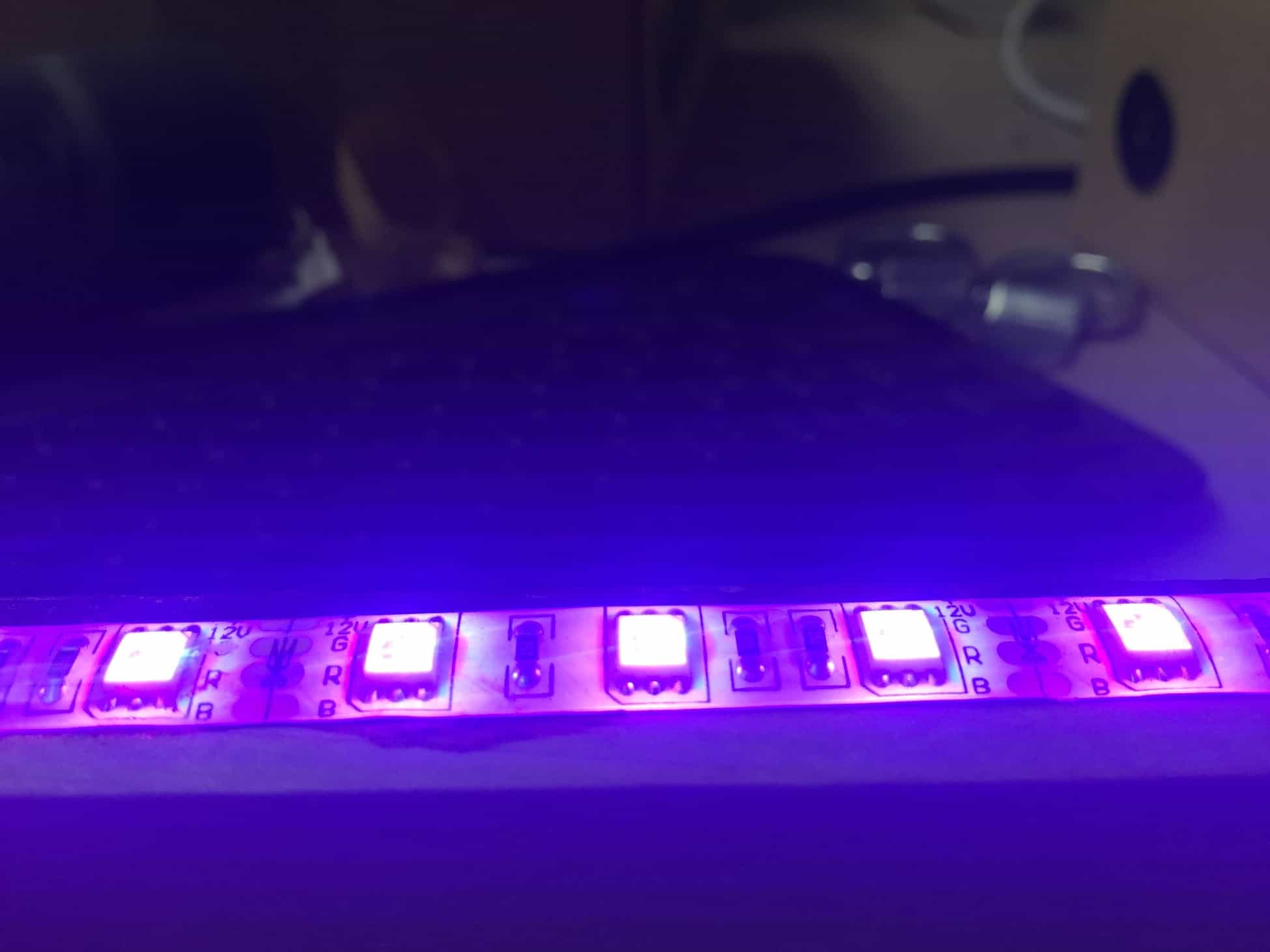
LEDs


The final milestone of this project is the installation of LED strips along both the interior and exterior of the frame that is controllable from my smartphone and Alexa.
Materials Used
- RGB LED strip (with adhesive backing)
- LED wifi adapter
- 12V power supply
- 2.4 ghz wifi router
- Scissors
Setup
Wrap LEDs along the exterior of the frame.
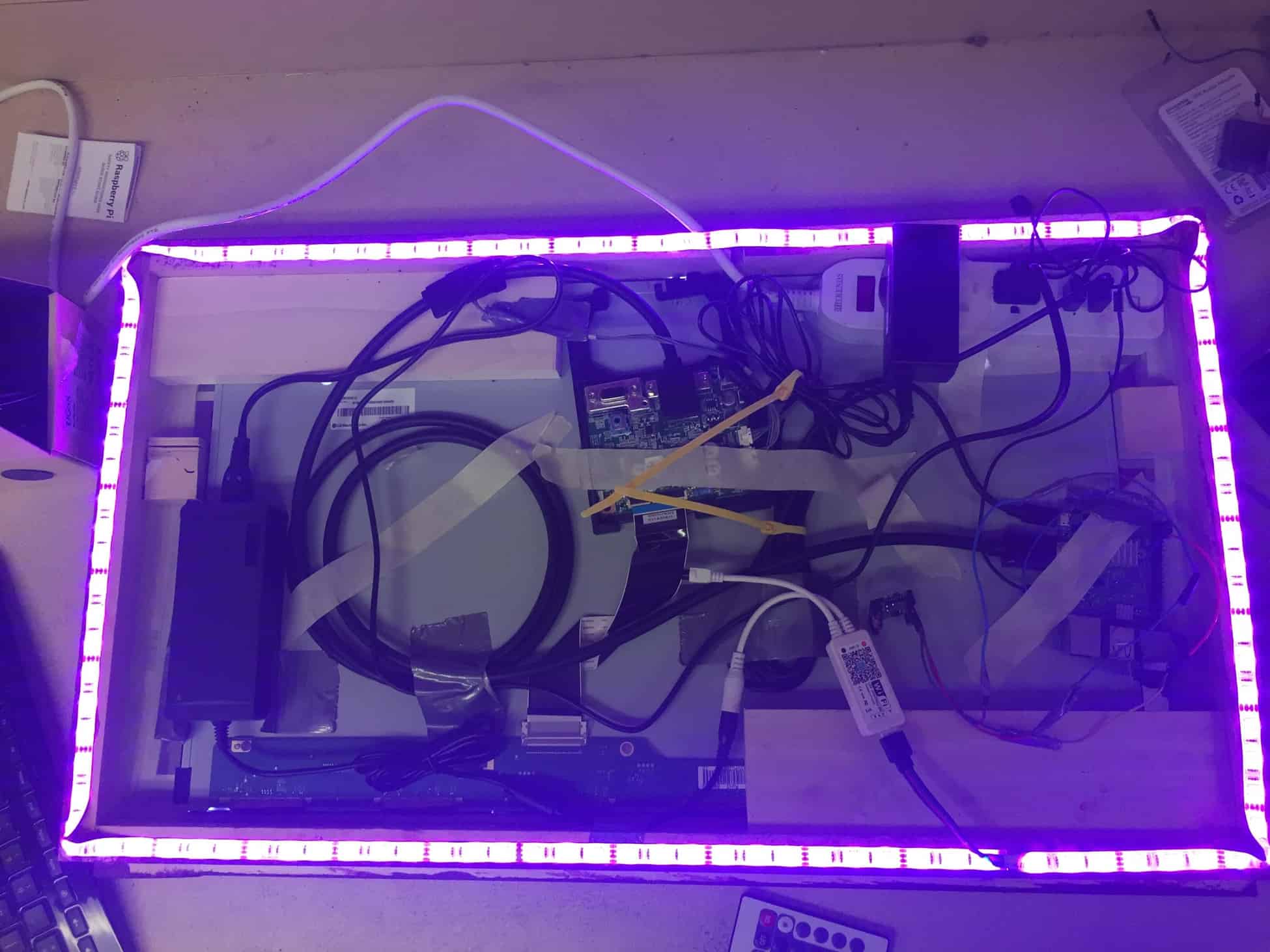
Wire the LEDs through the wifi adapter and provide power to the setup from the outlets.
Modifications
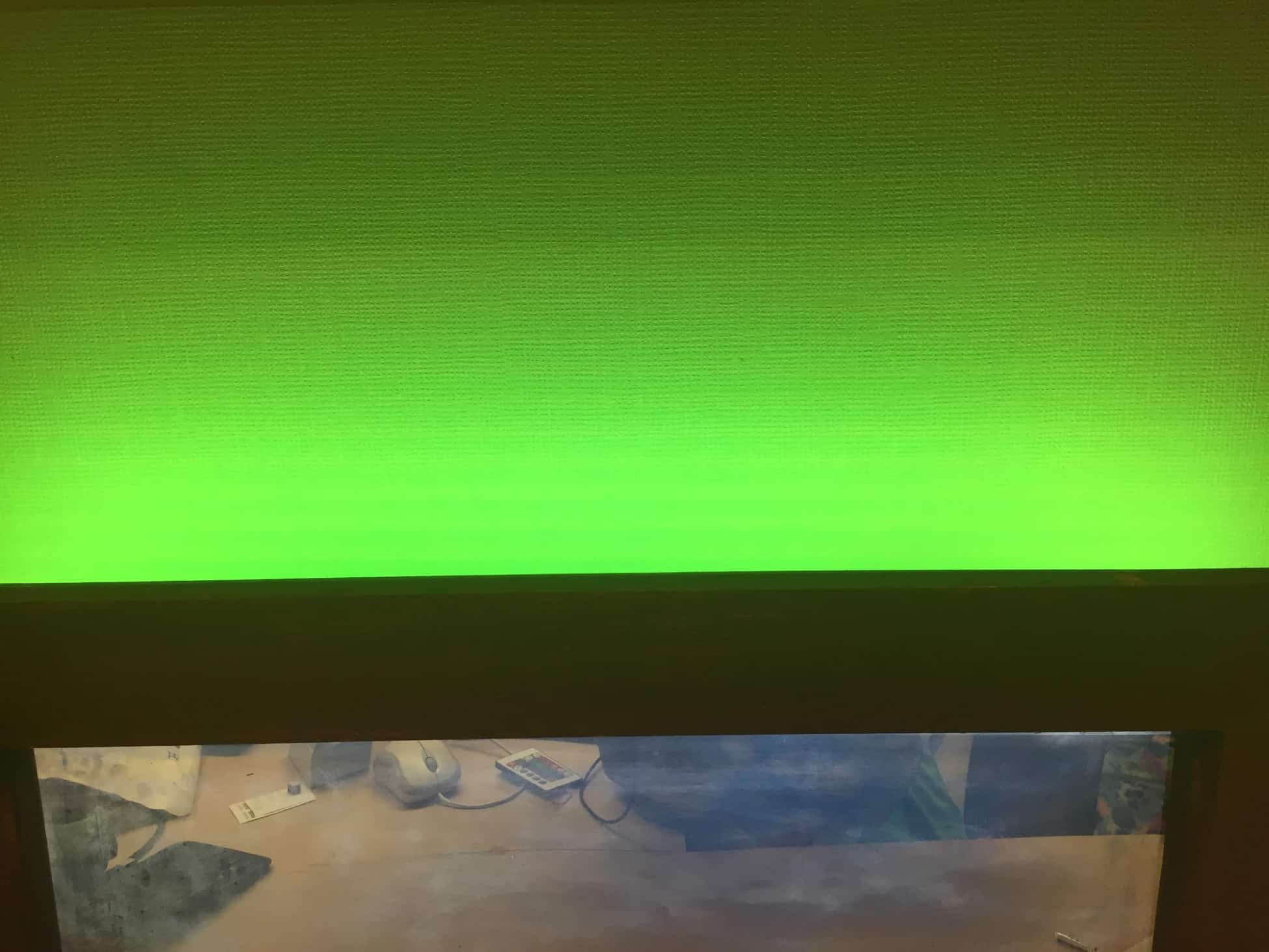
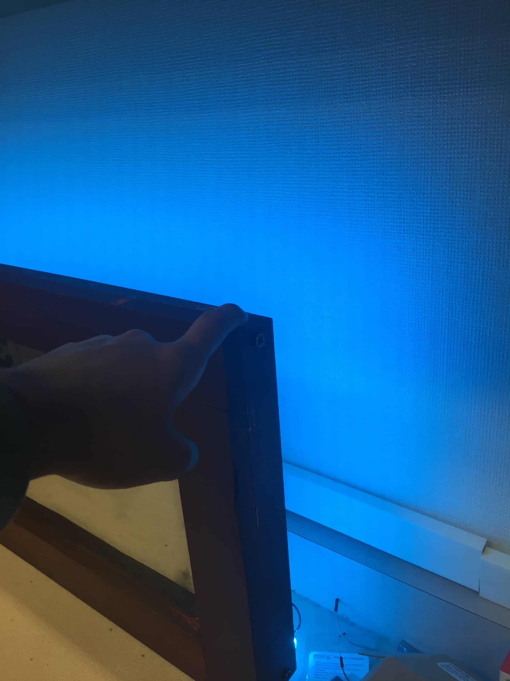
LED strips have been added to provide a stylistic flare to my mirror.
To further this modification is an incorporated wifi adapter for remote access from any smartphone to control the LEDs.
One upping remote access is integrating Alexa voice (from milestone #2) to control the LEDs via voice command.
Process to Reach Milestone
LED setup:
- Wrap the strip along the exterior of the frame
- Cut LEDs at this length
- Connect wifi adapter to the LEDs
- Connect wifi adapter to power supply
- Plug in power supply to outlet
Remote access from Smartphone:
- Download Magic Home Pro
- Create Magic Home account
- Power on LED strips
- Create new device
- Connect to the wifi adapter from the phone
- Network should be called LEDnet-xxxxxx
- If the wifi network does not appear, factor reset the adapter by connecting and disconnecting the adapter from power 4 times
- This should cause a strobe effect in the LEDs
- If the wifi network does not appear, factor reset the adapter by connecting and disconnecting the adapter from power 4 times
- Network should be called LEDnet-xxxxxx
- Go back into Magic Home app and connect to desired internet provider
- Must be 2.4 ghz (will not work with 5 ghz)
- Name the device
Alexa Voice control:
- On amazon Alexa app, enable Magic Home under the skills/games tab
- Log into Magic Home account
- Add the device previously named in the Magic Home app
Third Milestone
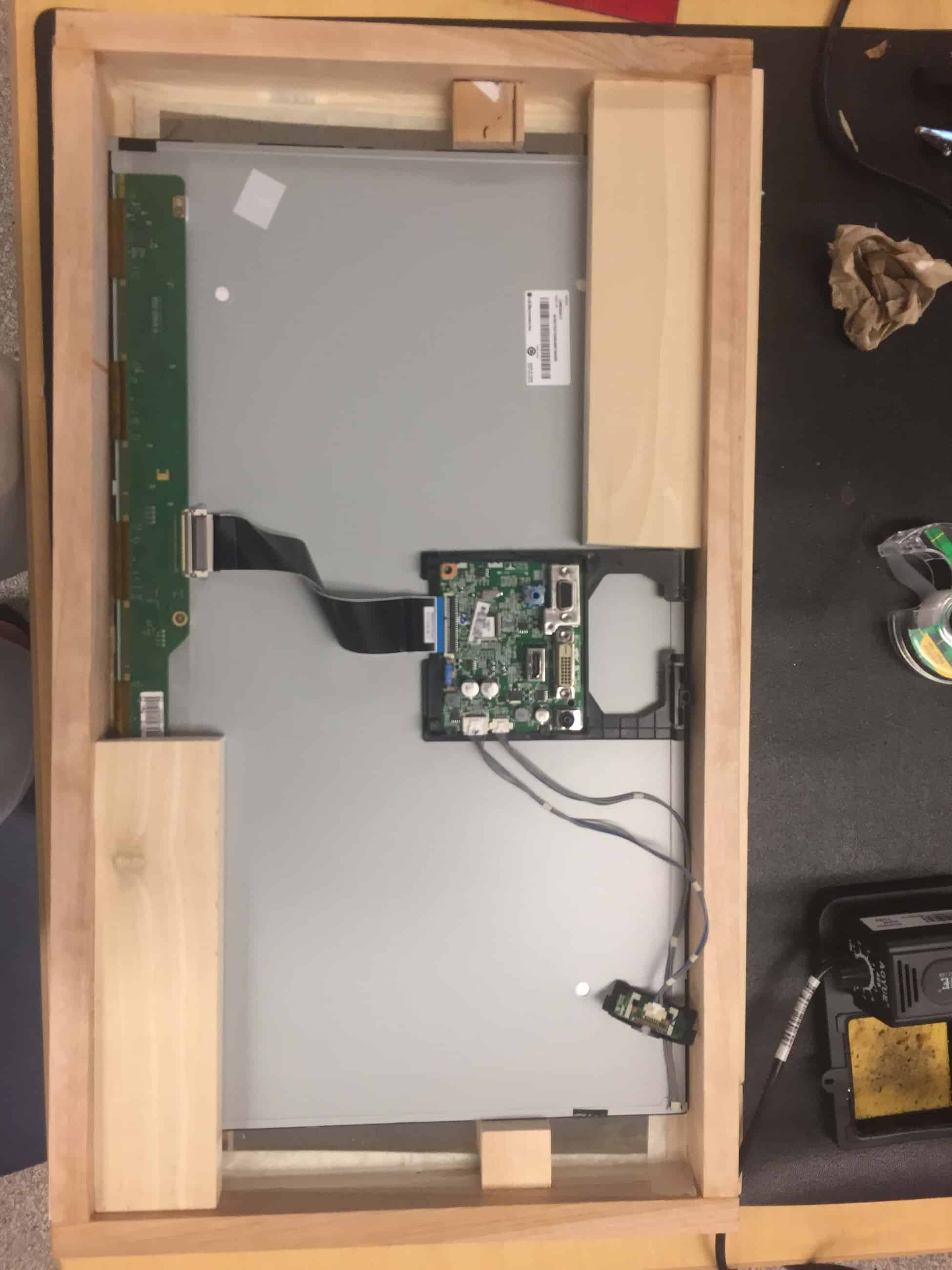
My third milestone includes the completion of the outside frame that includes a stained finish of the frame and the final put together of the mirrors components including the frame, the mirror, and the LED display.
Materials Used
- .75×1.5 wood (80 inches)
- 1×2.5 wood (80 inches)
- Saw
- Drill
- Screwdrivers
- Wood Screws
- Acrylic see-through mirror
- Power bar
- Electrical tape
- Super glue
- Wood glue
- Masking tape
- Wood finish
- Stain Brush
- Stirring stick
- File/Sandpaper
Setup
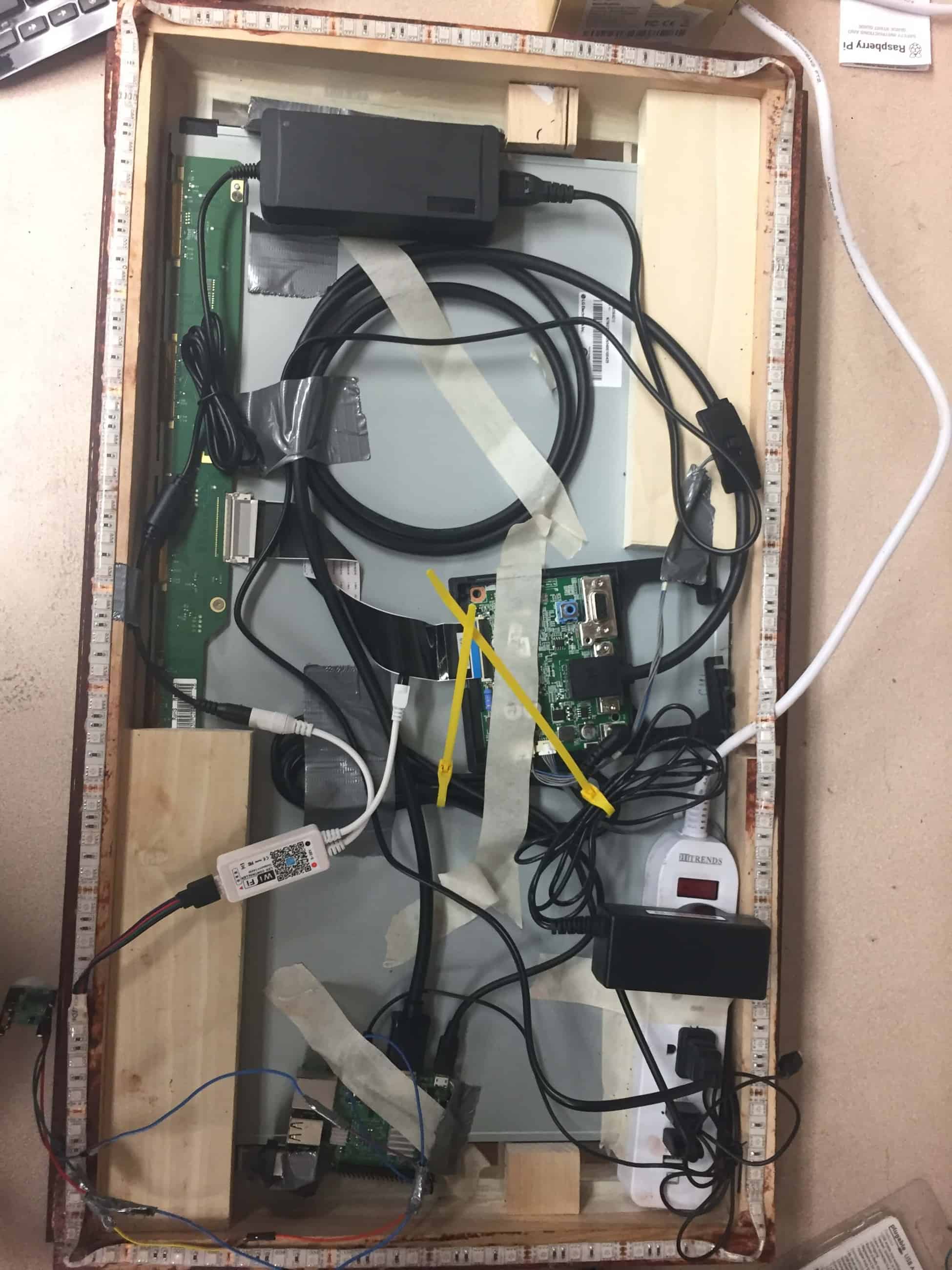
Inside the frame sits an acrylic mirror that is secured against it by both super glue and the LED monitor pressed against the back of it. The LED monitor is secured in place with extra wood from the construction frame.
Behind the LED display, all components requiring power are plugged into a power strip (pi, speaker, LED monitor) which is then plugged into a wall outlet. Electrical tape is used to secure many of the components to the back of the monitor or around the frame.
On the bottom side of the monitor the PIR sensor, direct power to the monitor, and speaker are all secured with either electrical tape or super glue to provide easy access and limited interference.
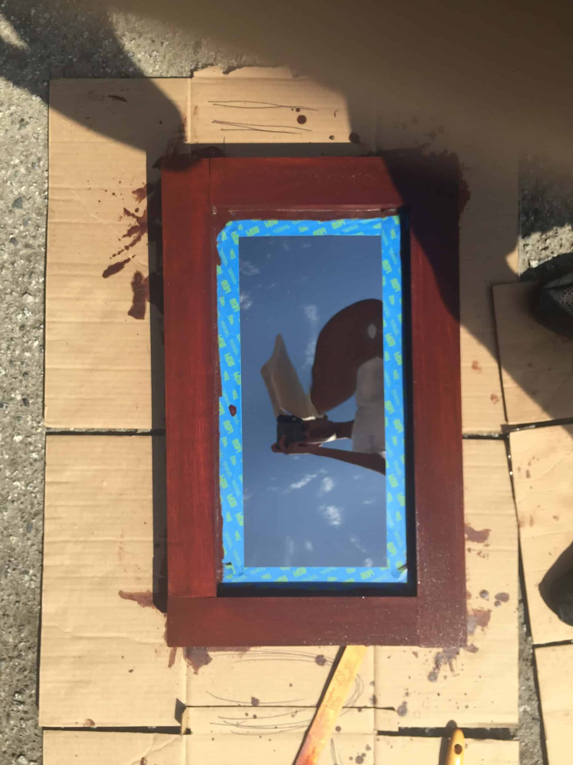
On top of cardboard, place the mirror frame face up for staining the surface.
Modifications
The PIR sensor wires were extended in length with an additional 3 male to male and female to female wires.
The monitor was stripped of its plastic casing to allow it to fit in the frame with ease.
Specific features of the modules have been tweaked to my preference.
The frame of the wood has been stained with wood finish to give it a darker color and match the furniture in my home.
Process to Reach Milestone
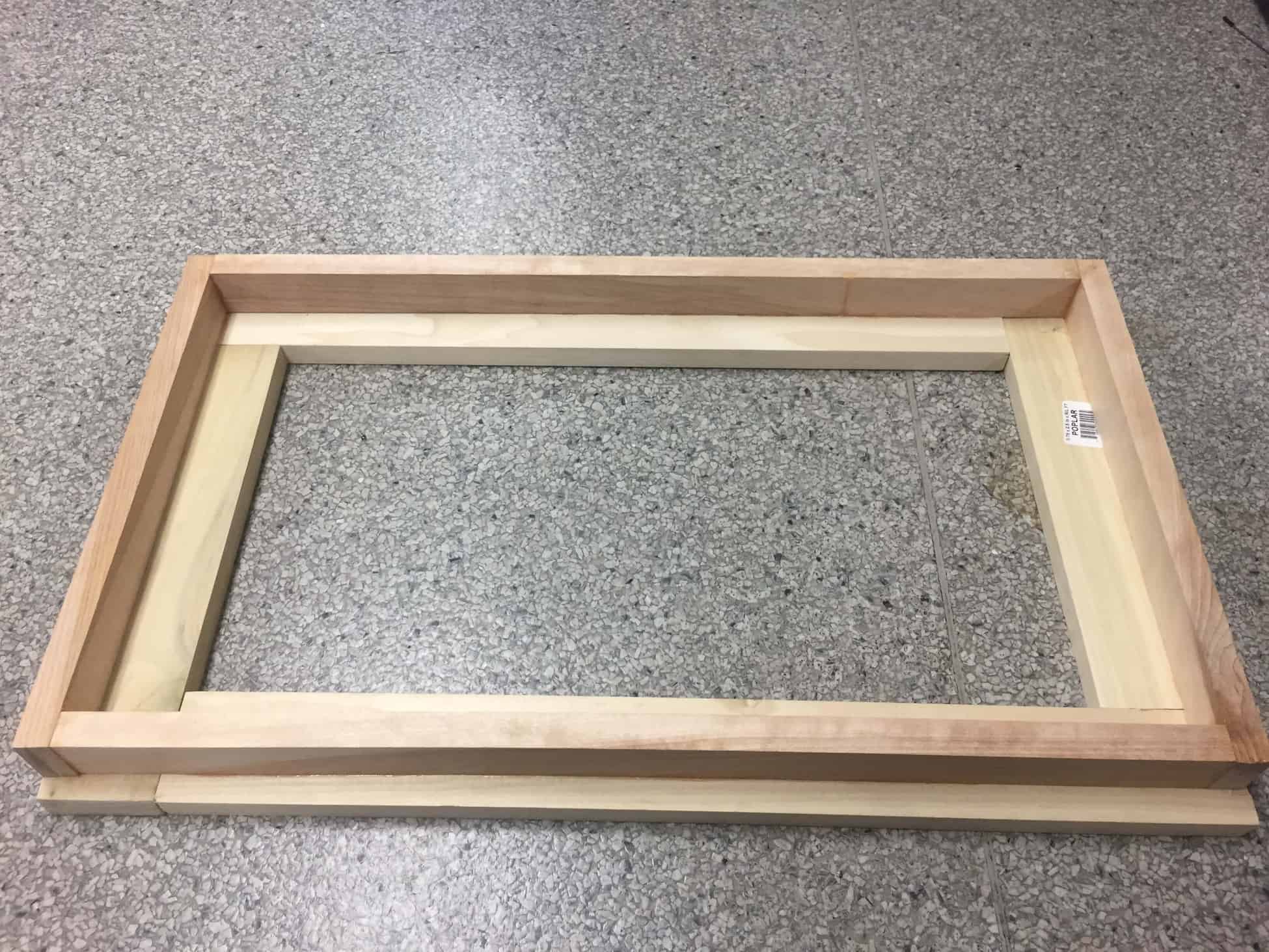
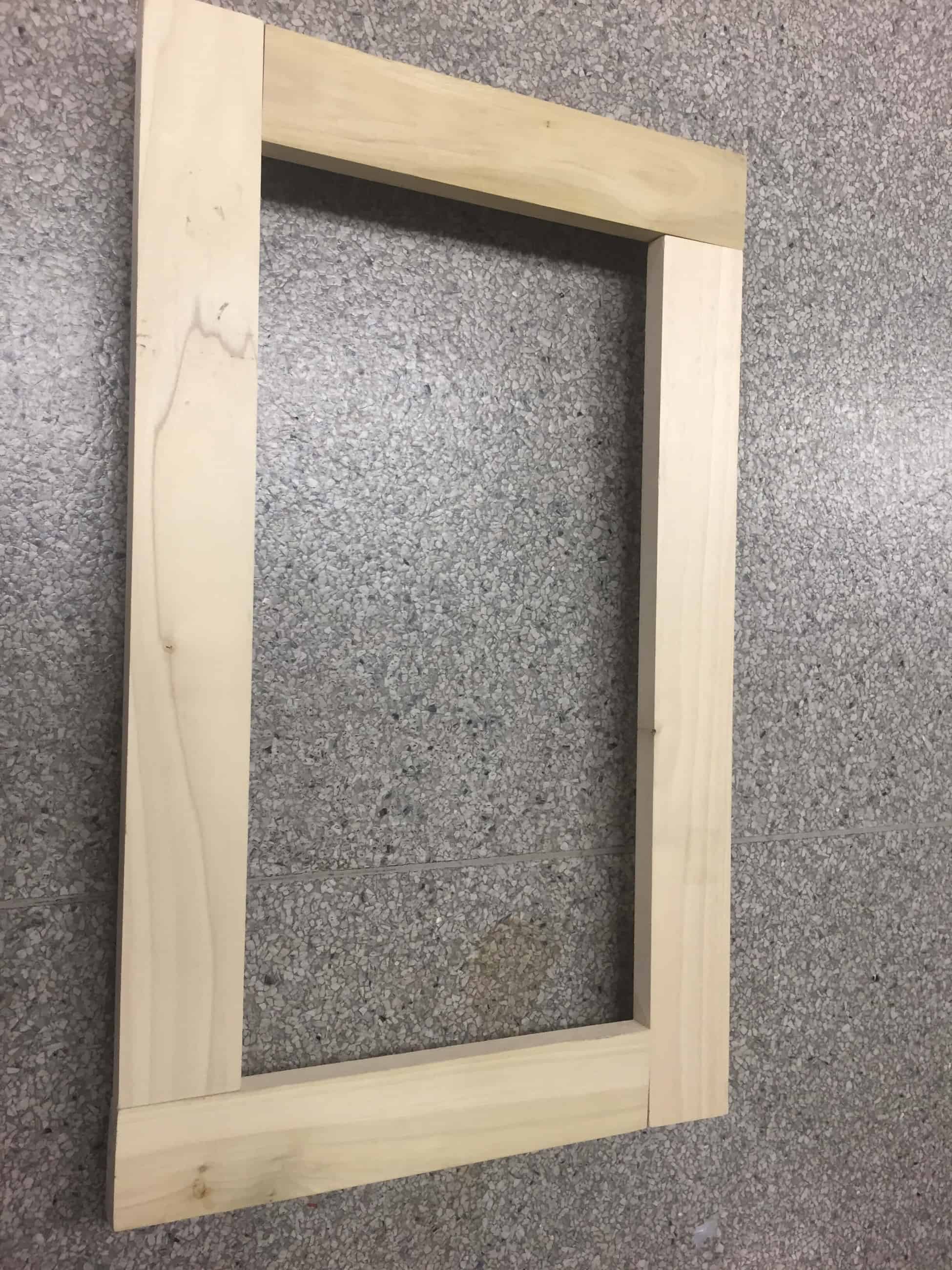
Frame Construction (2 parts):
- Backside
- cut 2 pieces of the .75×1.5 inch wood at 15 inches each
- cut 2 pieces of the .75×1.5 inch wood at 23.75 inches each
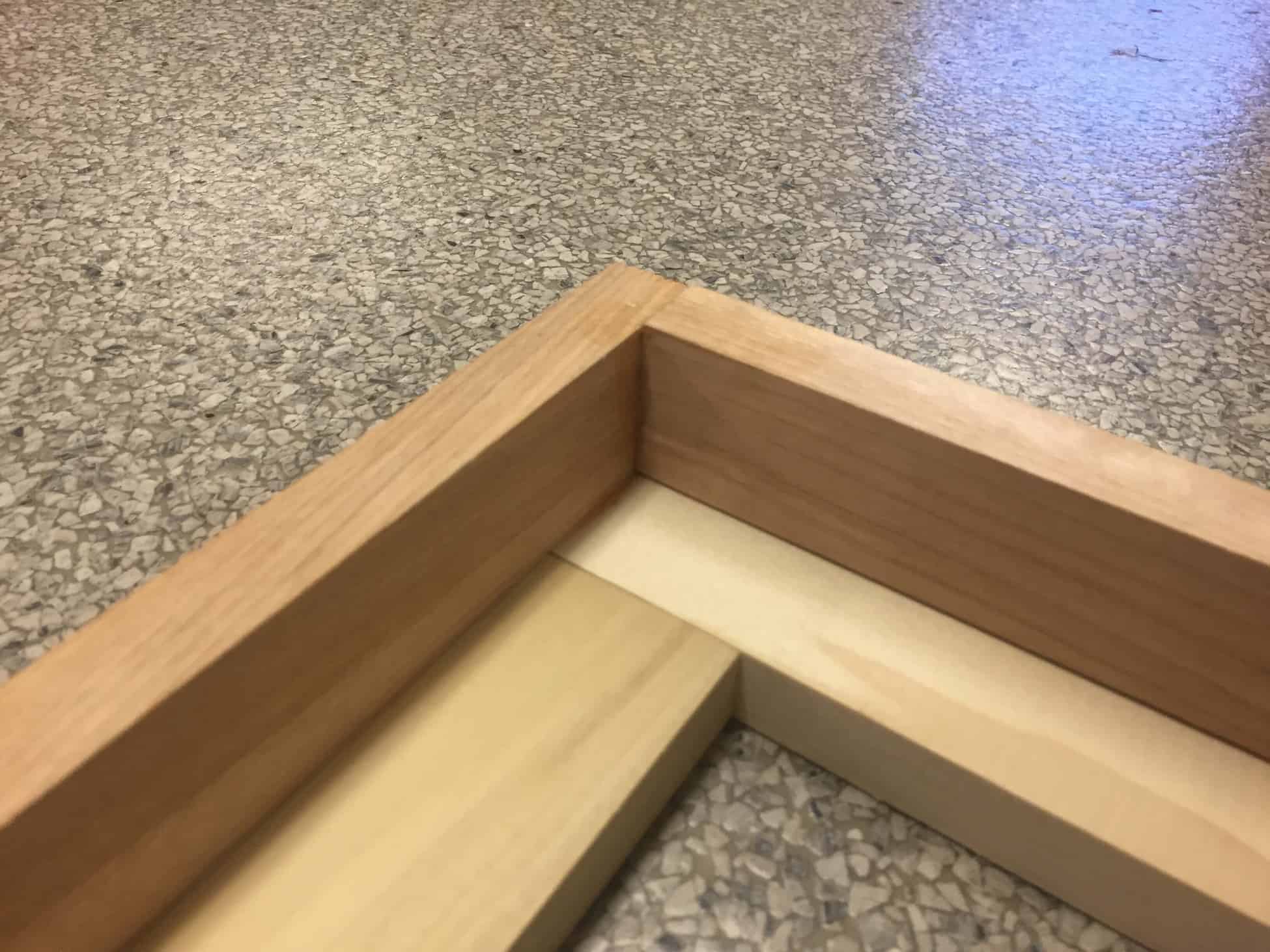
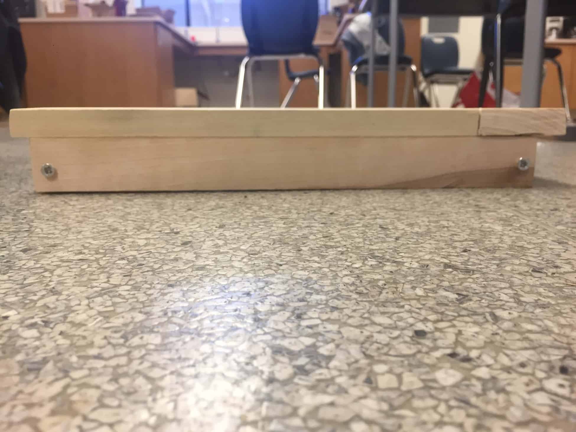
- Glue together at 90 degrees to form a rectangle
- Glue so that depth is 1.5 inch depth is provided to the back side (see frame images)
- Front side
- cut 2 pieces of the 1×2.5 inch wood at 13 inches each
- cut 2 pieces of the 1×2.5 inch wood at 23 inches each
- Glue each piece individually to the frame already constructed
- Glue so there is slight overhand on the top and bottom of the mirror to conceal the frame (see frame images)
- Sand or file the edges to fit the corners together at the proper length
Smart Mirror put together:
- After the frame has been constructed, place the mirror into frame
- If mirror is too big, trim one edge of it using wire cutters
- The edge cut does not have to be perfectly linear as it will be concealed once placed in the frame
- Cover cut edge with masking tape to prevent dispersion of the cracks
- Secure the mirror in place with super glue and masking tape
- If mirror is too big, trim one edge of it using wire cutters
- Strip the monitor of its plastic casing
- In most cases your hands can be used to do this
- Behind the mirror place the LED monitor in the center
Wood Finish:
- Outside, set up cardboard on the ground
- Stir the wood finish until it is relatively liquid
- Cover the interior of the mirror with plastic and secure with masking tape along the edges to prevent damage to the surface of the mirror
- Dip the stain brush into the finish and apply consistent layers of finish to the wood
- Strokes should be long and in the same direction
Second Milestone

My second milestone for the Smart Mirror is the addition of personally selected modules, integration of Alexa voice control, and a fully functioning PIR sensor that turns the LED display on and off based on motion in the room.
Materials Used
- Speaker with 3.5 mm jack
- USB Microphone
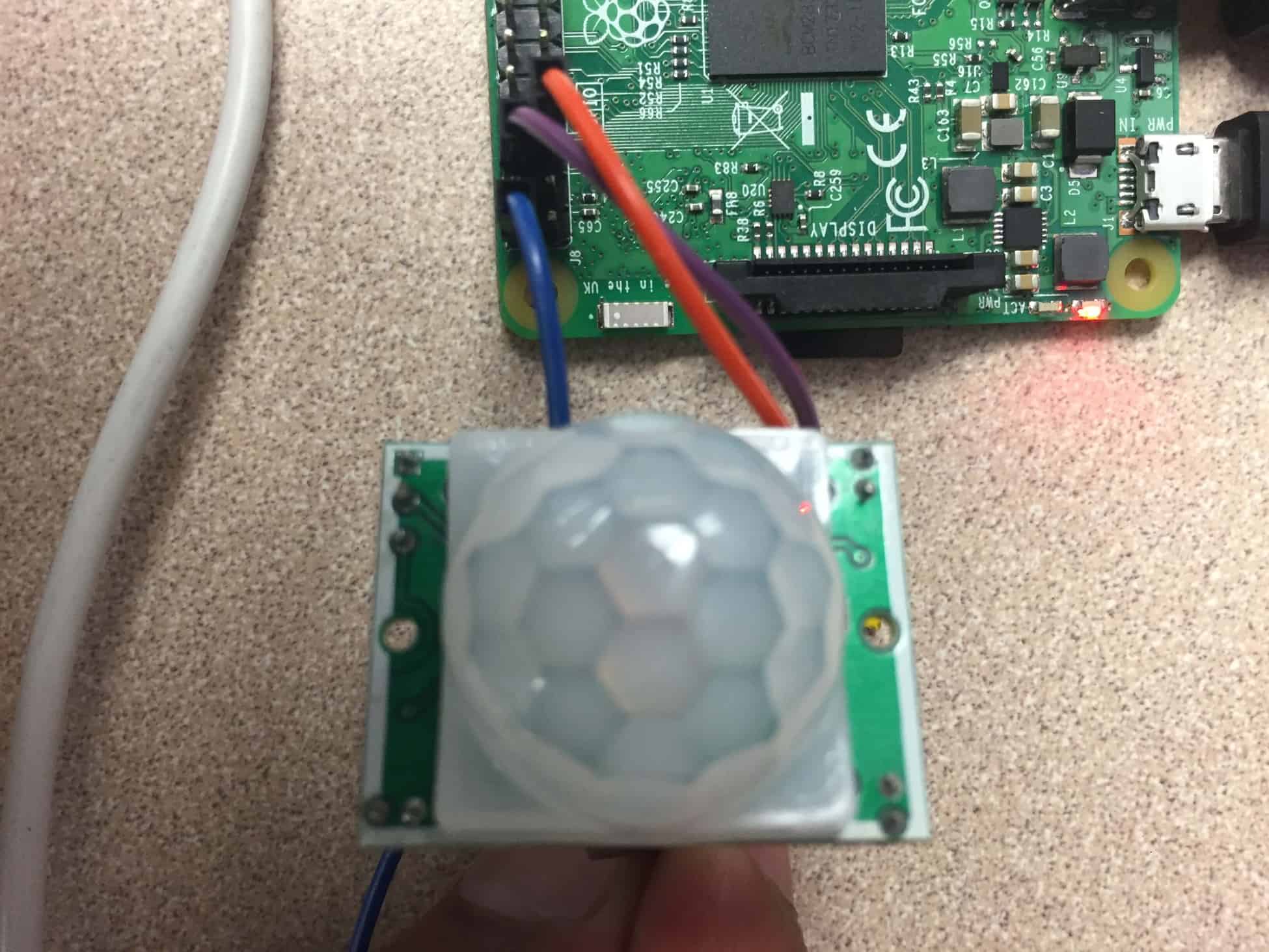
- HC-SR501 PIR Sensor
- 3 female-female wires
Setup
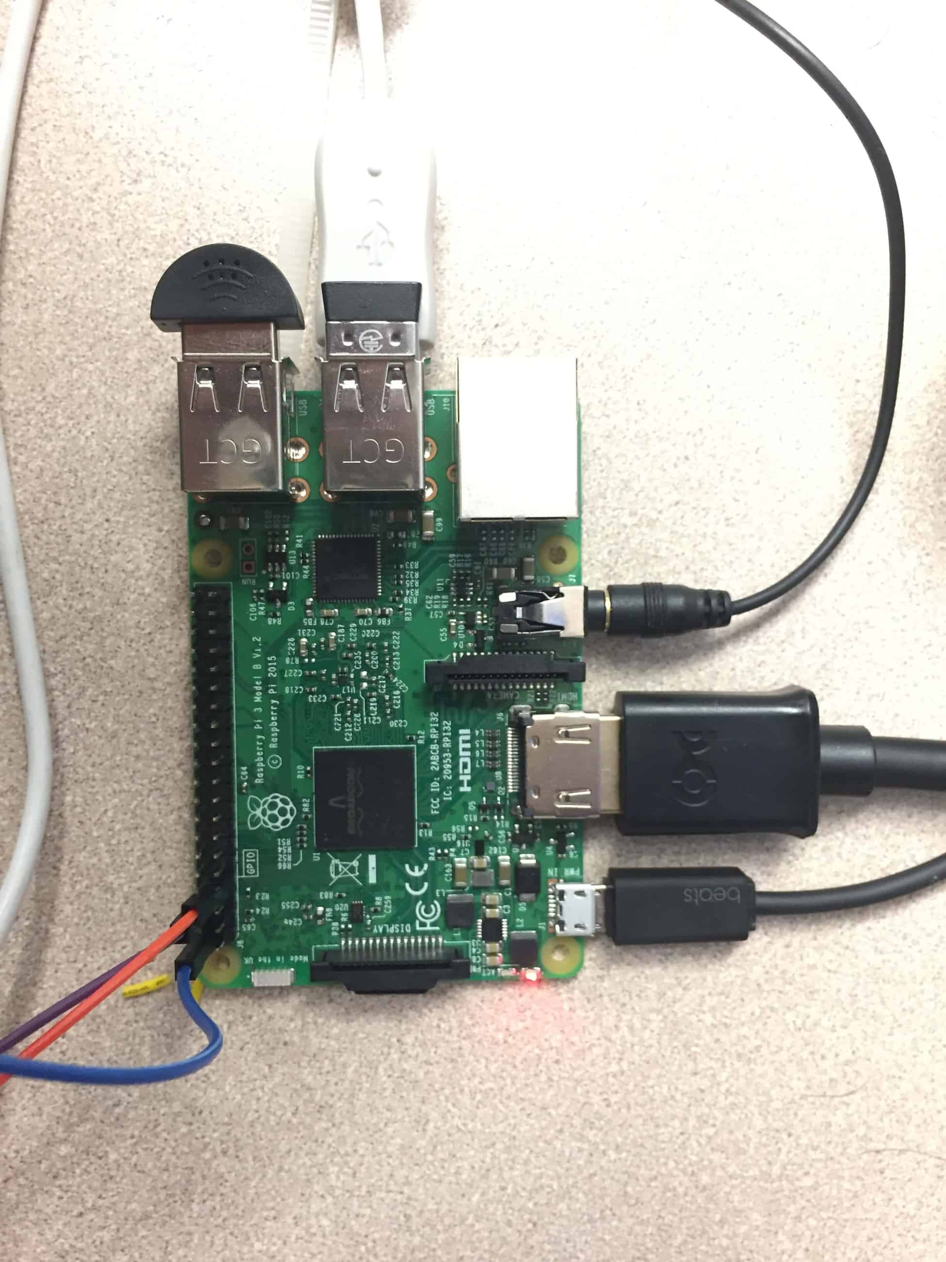
Since the last milestone, various modifications have been made to the setup of the pi. A USB mic is now connected as well as 3.5mm jack for the speaker. In order to permit the usage of the PIR sensor, the GPIO pins have been utilized. A the ground, the power, and pin 7 have been selected accordingly for hardware aspect of the setup.
Modifications
Alexa Voice Control is now integrated within the raspberry pi separate from the the MagicMirror modules. Separate from its compatibility with google calendar (which was previously setup in my first milestone), Alexa serves as an additional feature that fits well with the general purposes of the mirror by providing convenience to the user.
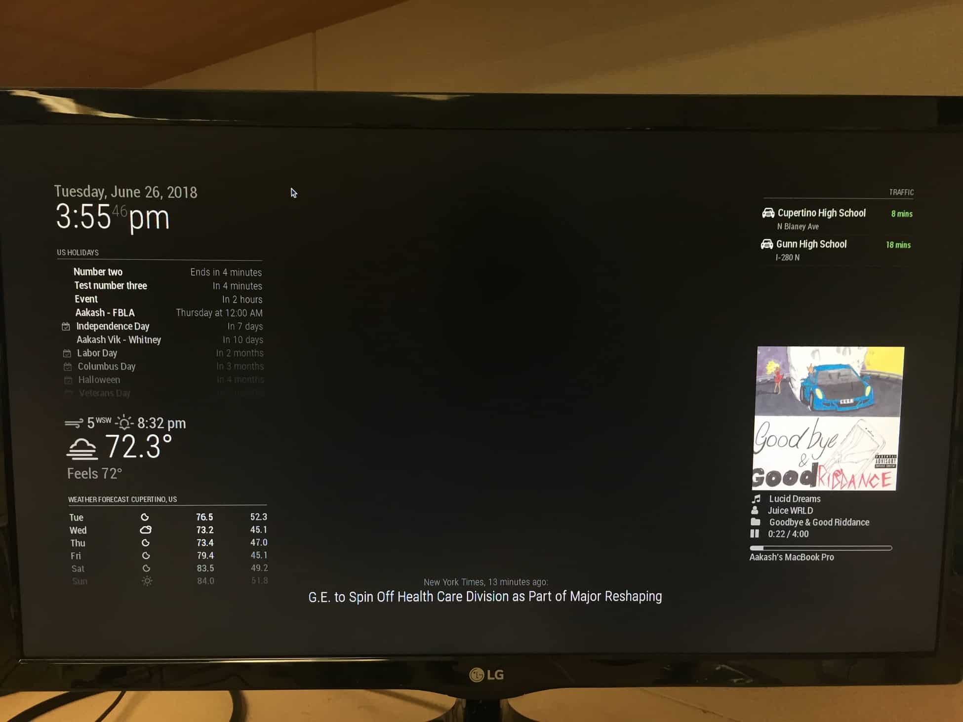
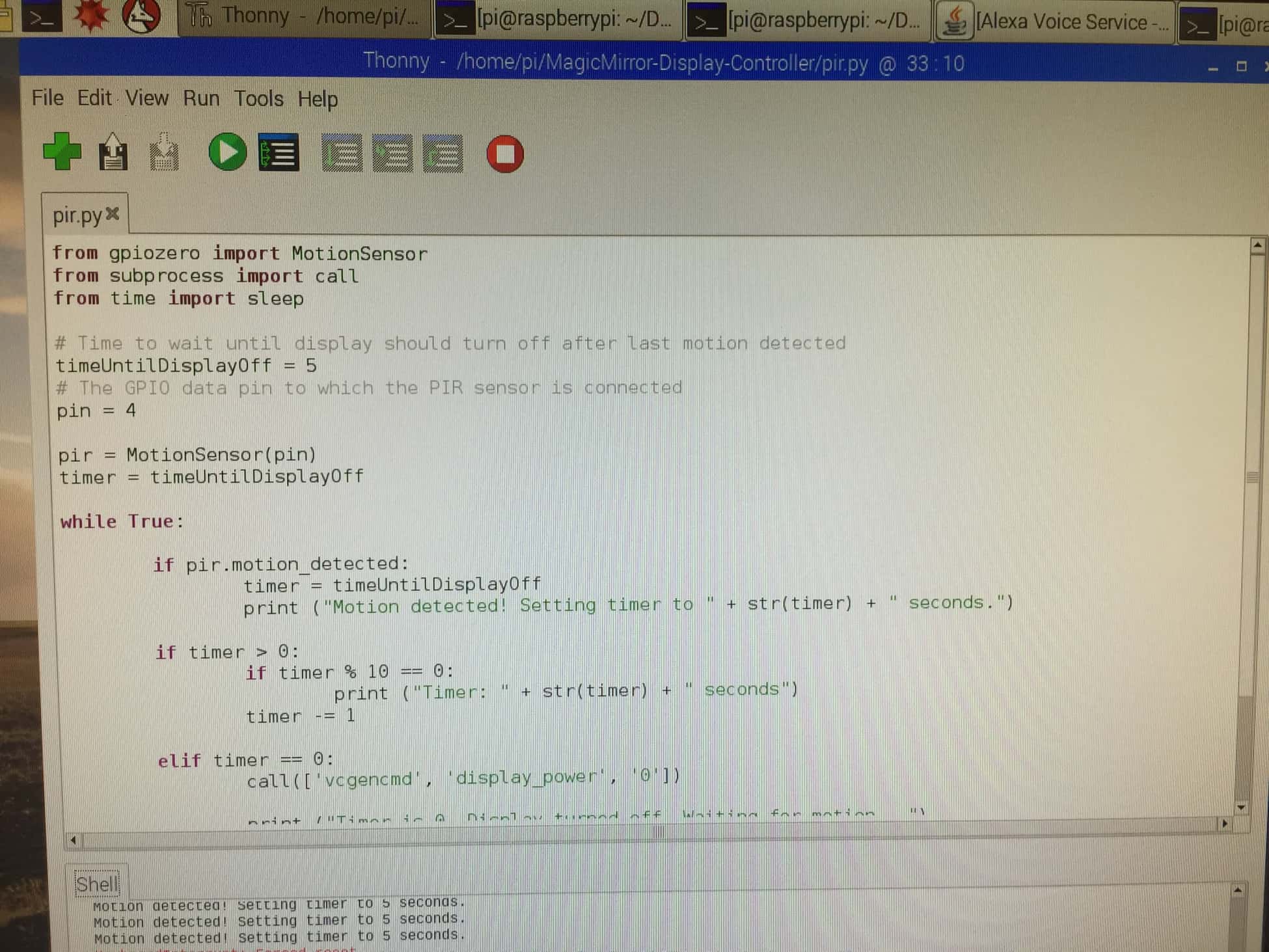
Also incorporated is the PIR sensor that controls the HDMI power connection between the pi and the monitor. By adjusting the code accordingly, I can specifically select the time interval of the shutoff mechanism. Currently, the monitor is set to shut off after 10 seconds without motion; however I will most likely set this value to 600 seconds (10 mins) when mounted. This conserves power and only function when I am near or around the Mirror.
Process to Reach Milestone
Modules:
- After the basic construction of standard display for the Magic Mirror was research into specific modules I’d like to incorporate.
- Spotify Now Playing Module
- Installing file from GitHub
- Creation of a Spotify developer area to get client ID and client secret
- Installing modules onto config file of MagicMirror
- I have selected to show the cover art of the music playing. This can be controlled from the configuration file of the module itself
- My Commute Module
- Installing file from Github
- Creating a developer account to get google maps api key
- Entering starting point and destination
- Entering mode of transportation
LINK TO MODULES: https://github.com/MichMich/MagicMirror/wiki/3rd-party-modules
Alexa Voice:
- I selected Alexa Voice over Google Assistant because there was ultimately a more comprehensive guide to install Alexa. Upon review of the two choices, Alexa seemed to provide more accessibility and general compatibility as I can easily access the device from my smartphone.
- A developer account was necessary to access the open source Alexa software. When making a developer account, a project was created where I was given a specific client ID and client secret.
- Installing the Alexa Voice script through the terminal from github
- Entering client credentials to access project from pi
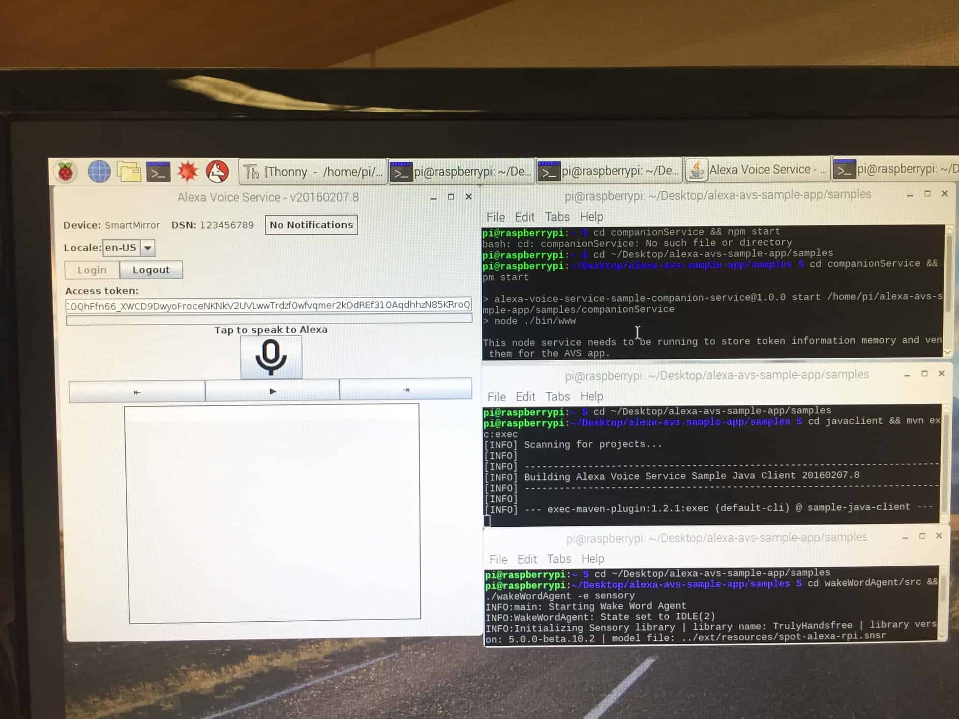
- Opening 3 terminal windows
- Bring up web service to authorize sample app
- Run sample app that communicates with Alexa voice
- Running sample app with wake word engine “Alexa”
- Once all three terminals are setup, Alexa voice service should fully function
FULL INSTALLATION GUIDE: https://github.com/alexa/alexa-avs-sample-app/wiki/Raspberry-Pi
PIR Sensor:
- After spending two days attempting to install the PIR sensor as a module into the Magic Mirror module folder itself, I discovered it might be easier to run python code separate from the Magic Mirror
- From GitHub, I installed python code that serves as an HDMI controller for the monitor, not specifically the mirror
- The actual connectivity between the pi and PIR sensor was relatively simple
- GND on the PIR goes to pin 6
- VCC on the PIR goes to pin 2
- OUT on the PIR goes to pin 7
- It doesn’t matter where the output goes on the pi as long as you accommodate for this in the code
LINK TO PYTHON CODE: https://github.com/deg0nz/MagicMirror-Display-Controller
Altering Display:
- From the config.js file of the Magic Mirror, the specific locations and display of the modules can be altered based on user preference
- Installing file from GitHub
- Creation of a Spotify developer area to get client ID and client secret
- Installing modules onto config file of MagicMirror
- I have selected to show the cover art of the music playing. This can be controlled from the configuration file of the module itself
- Installing file from Github
- Creating a developer account to get google maps api key
- Entering starting point and destination
- Entering mode of transportation
- Bring up web service to authorize sample app
- Run sample app that communicates with Alexa voice
- Running sample app with wake word engine “Alexa”
- GND on the PIR goes to pin 6
- VCC on the PIR goes to pin 2
- OUT on the PIR goes to pin 7
- It doesn’t matter where the output goes on the pi as long as you accommodate for this in the code
First Milestone
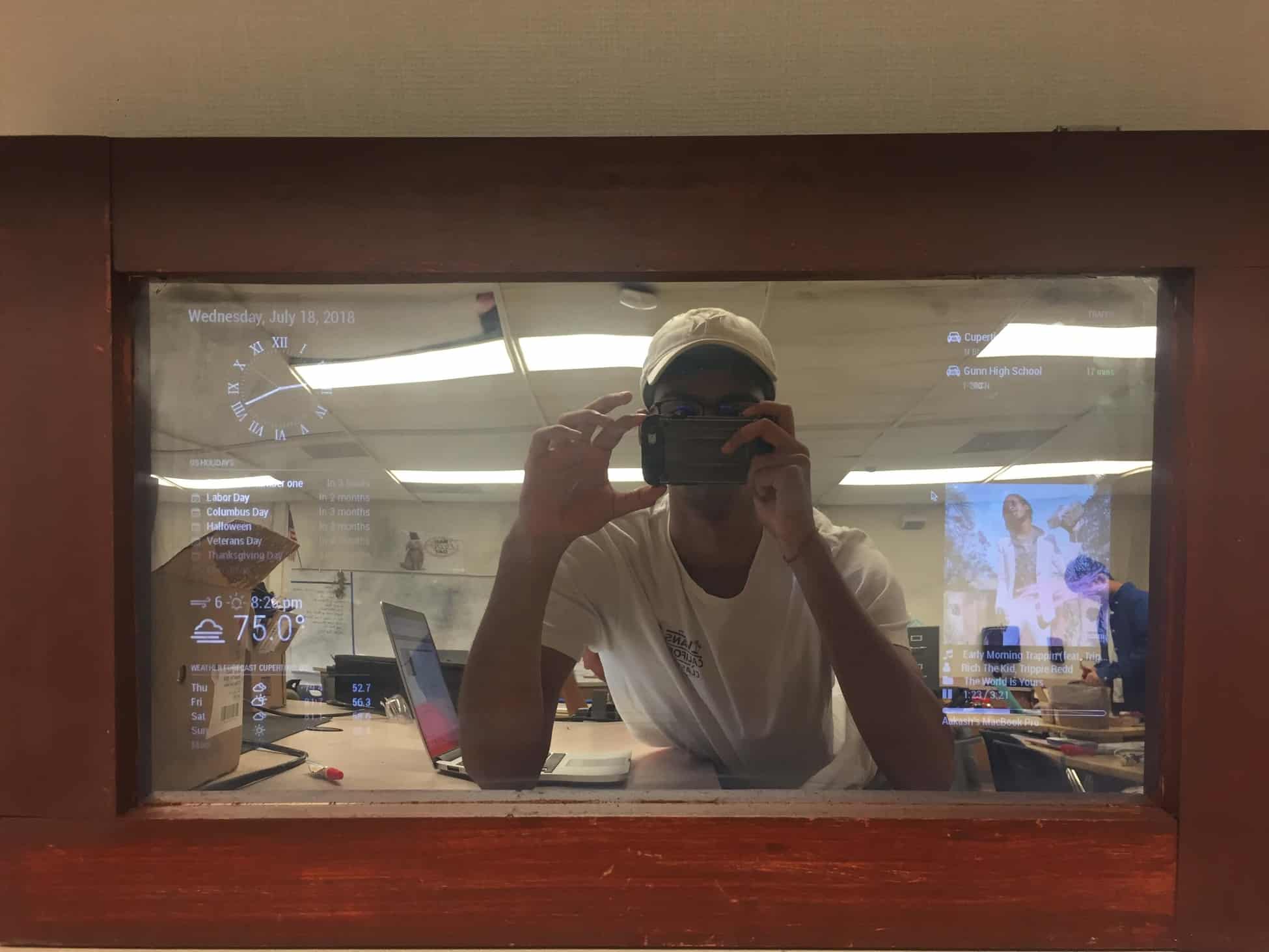
My first milestone for the Smart Mirror is finishing the complete setup of the standard display with the addition of my personal google calendar.
Materials Used
- LED display
- USB mouse and bluetooth keyboard
- Raspberry Pi 3
- HDMI cable
- Micro SD card with Adapter
Setup
The raspberry pi is controlled via a USB mouse and a bluetooth keyboard. To display the pi itself, an HDMI cable connect the pi to the LED monitor. The pi is powered by a micro USB cable plugged into a wall outlet for continuous power. Similarly, the monitor is plugged into an external outlet for power.
The remote access to the pi is conducted through VNC viewer and displayed on my personal laptop. After the the VNC server was installed on the pi, display on my laptop is accessed through the IP address of the pi.
Modifications
After the core code was downloaded from a github open source file, I made minor altercations to the code to tailor the display to my preference.
The default setup of the display come with a generic display of US holidays. To personalize my project a little, I added the link of my google calendar into the configuration code for the display.
Process to Reach Milestone
Raspberry Pi Setup:
- Installation Raspbian onto micro SD
- Set-up of VNC viewer for remote access to pi from laptop (not necessary unless there is not access to monitor/mouse and keyboard)
How to setup VNC viewer: https://www.youtube.com/watch?v=JYKZjUgtOYw&t=239s
Mirror Setup:
- Install of MagicMirror software github
- Getting and installing custom API key for weather module
- Create free account with openweathermap
- Get API key and input into configuration code file
- Implementing personal calendar into display code
Magic Mirror Base Software: https://github.com/MichMich/MagicMirror
Weather API Key: https://openweathermap.org/
- Create free account with openweathermap
- Get API key and input into configuration code file
Starter Project
Device

For my starter project, I have constructed the TV-B-Gone. Powered by two AA batteries, current is sent to various components of the circuit board including a ceramic oscillator, a capacitor, an LED, 4 IR LEDs, a micro-controller, an PNP transistor, and 4 NPN transistors.
When activate the device emits IR LED patterns toward the TV, the TV interprets it as a “turn off” function similar to a TV remote. This is possible via the pre-programed micro-controller that contains the off code for most TV manufacturers.
Throughout the manufacturing process, I learned much about the purposes of the individual components of the circuit board. Additionally, I had the opportunity to practice with soldering.