Self Dancing Car
Hi my name is Caleb and I am currently a rising sophomore at Uncommon Charter School. My main project is a self dancing car that uses a app to control it. I chose this project because I am interested in learning about voice controlled technology.
Engineer
Caleb S
Area of Interest
Electrical Engineering
School
Uncommon Charter High School
Grade
Incoming Sophomore
Reflection
Before coming to Bluestamp, I thought engineering was just building stuff from premade instructions. I did not have much experience in the techniques you need to do engineering. However, after coming here I was able to learn tangible skills like soldering and programming.More importantly I learned it’s not just one idea making projects its combining many different ideas together and all of them integrating with each other. I was able to realize that later in my life I want to utilize the skills I have I gathered to become a robotics engineer.I want to innovate the world with my ideas and with this experience under my belt. Finally I learned engineering is not just a job or hobby it is a way of life.
Final Milestone
#include <ESP8266WiFi.h>
WiFiClient client;
WiFiServer server(80);
const char* ssid = “TP-LINK_2856”;
const char* password = “77707123”;
String command =””; // Command received from Android device
// Set Motor Control Pins
int rightMotor2 = 13; // D7 – right Motor –
int rightMotor1 = 15; // D8 – right Motor +
int leftMotor2 = 0; // D3 – left Motor –
int leftMotor1 = 2; // D4 – left Motor +
int eneLeftMotor = 12; // D6 – enable Mortor Left
int eneRightMotor = 14; // D5 – enable Mortor Right
void setup()
{
Serial.begin(115200);
pinMode(eneLeftMotor, OUTPUT);
pinMode(eneRightMotor, OUTPUT);
pinMode(leftMotor1, OUTPUT);
pinMode(leftMotor2, OUTPUT);
pinMode(rightMotor1, OUTPUT);
pinMode(rightMotor2, OUTPUT);
digitalWrite(eneLeftMotor,LOW);
digitalWrite(eneRightMotor,LOW);
digitalWrite(leftMotor1,LOW);
digitalWrite(leftMotor2,LOW);
digitalWrite(rightMotor1,LOW);
digitalWrite(rightMotor2,LOW);
connectWiFi();
server.begin();
}
void loop()
{
client = server.available();
if (!client) return;
command = checkClient ();
if (command == “forward” || command == “frente” || command == “a frente”) forwardMotor();
else if (command == “reverse” || command == “reverso”|| command == “voltar”) reverseMotor();
else if (command == “left” || command == “esquerda”) leftMotor();
else if (command == “right” || command == “direita”) rightMotor();
else if (command == “stop” || command == “pare” || command == “parar” || command == “parando”) stopMotor();
sendBackEcho(command); // send command echo back to android device
command = “”;
}
/* command motor forward */
void forwardMotor(void)
{
digitalWrite(eneLeftMotor,HIGH);
digitalWrite(eneRightMotor,HIGH);
digitalWrite(leftMotor1,HIGH);
digitalWrite(leftMotor2,LOW);
digitalWrite(rightMotor1,HIGH);
digitalWrite(rightMotor2,LOW);
}
/* command motor backward */
void reverseMotor(void)
{
digitalWrite(eneLeftMotor,HIGH);
digitalWrite(eneRightMotor,HIGH);
digitalWrite(leftMotor1,LOW);
digitalWrite(leftMotor2,HIGH);
digitalWrite(rightMotor1,LOW);
digitalWrite(rightMotor2,HIGH);
}
/* command motor turn left */
void leftMotor(void)
{
digitalWrite(eneLeftMotor,HIGH);
digitalWrite(eneRightMotor,HIGH);
digitalWrite(leftMotor1,LOW);
digitalWrite(leftMotor2,HIGH);
digitalWrite(rightMotor1,HIGH);
digitalWrite(rightMotor2,LOW);
}
/* command motor turn right */
void rightMotor(void)
{
digitalWrite(eneLeftMotor,HIGH);
digitalWrite(eneRightMotor,HIGH);
digitalWrite(leftMotor1,HIGH);
digitalWrite(leftMotor2,LOW);
digitalWrite(rightMotor1,LOW);
digitalWrite(rightMotor2,HIGH);
}
/* command motor stop */
void stopMotor(void)
{
digitalWrite(eneLeftMotor,LOW);
digitalWrite(eneRightMotor,LOW);
digitalWrite(leftMotor1,LOW);
digitalWrite(leftMotor2,LOW);
digitalWrite(rightMotor1,LOW);
digitalWrite(rightMotor2,LOW);
}
/* connecting WiFi */
void connectWiFi()
{
Serial.println(“Connecting to WIFI”);
WiFi.begin(ssid, password);
while ((!(WiFi.status() == WL_CONNECTED)))
{
delay(300);
Serial.print(“..”);
}
Serial.println(“”);
Serial.println(“WiFi connected”);
Serial.println(“NodeMCU Local IP is : “);
Serial.print((WiFi.localIP()));
}
/* check command received from Android Device */
String checkClient (void)
{
while(!client.available()) delay(1);
String request = client.readStringUntil(‘\r’);
request.remove(0, 5);
request.remove(request.length()-9,9);
return request;
}
/* send command echo back to android device */
void sendBackEcho(String echo)
{
client.println(“HTTP/1.1 200 OK”);
client.println(“Content-Type: text/html”);
client.println(“”);
client.println(“<!DOCTYPE HTML>”);
client.println(“<html>”);
client.println(echo);
client.println(“</html>”);
client.stop();
delay(1);
}
Second Milestone
For my second milestone, I was able to show the robot was able to follow a pre programmed routine. This was my first time having to use Arduino code so intensely. I had to learn a lot of new things about coding.I started out by looking at many different example codes to see how to structure my code.At first, I thought i had found the correct code to make the dance but it was not so easy.The code did not work and I realized I had to make custom code to make the robot do what I want it to do.I started out with making functions to make the robot move.Functions are used to perform the same action multiple times without writing the same thing over and over again. The biggest challenge that I faced was trying to get the timing in the code to be right. To get the robot in the dance mode I had put each command in the perfect order. However getting it in the order was not that easy. I was able to overcome this I went to many trials and error but I finally got it to work. By not giving up I was able to learned that you cannot expect everything to be right the very first time. Engineering takes iteration and commitment and a little creativity.
}void moveforward(){
digitalWrite(enablePin,HIGH);
digitalWrite(motorRight,HIGH);
digitalWrite(motorRight2,LOW);
digitalWrite(enablePin2,HIGH);
digitalWrite(motorLeft,LOW);
digitalWrite(motorLeft2,HIGH);
}void dontmove()
digitalWrite(enablePin,HIGH);
digitalWrite(motorRight,LOW);
digitalWrite(motorRight2,LOW);
digitalWrite(enablePin2,HIGH);
digitalWrite(motorLeft,LOW);
digitalWrite(motorLeft2,LOW);
}void movebackward(){Serial.print(“movebackward”);
digitalWrite(enablePin,HIGH);
digitalWrite(motorRight,LOW);
digitalWrite(motorRight2,HIGH);
digitalWrite(enablePin2,HIGH);
digitalWrite(motorLeft,HIGH);
digitalWrite(motorLeft2,LOW);
}void turnleft(){ Serial.print(“moveleft”);
digitalWrite(enablePin,HIGH);
digitalWrite(motorRight,LOW);
digitalWrite(motorRight2,HIGH);
digitalWrite(enablePin2,HIGH);
digitalWrite(motorLeft,LOW);
digitalWrite(motorLeft2,HIGH);
}void turnright(){Serial.print(“moveright”);
digitalWrite(enablePin,HIGH);
digitalWrite(motorRight,LOW);
digitalWrite(motorRight2,LOW);
digitalWrite(enablePin2,HIGH);
digitalWrite(motorLeft,HIGH);
digitalWrite(motorLeft2,LOW);
First Milestone
My main project is a voice controlled robot. My first milestone was to show the motors working. I controlled the robot to move forward and backward at my command. At first, I tried connecting wires to the breadboard and the motors from a tutorial seen here. After successfully connecting the wires, I tried connecting the breadboard to the nodemcu. The nodemcu is a microcontroller used to control the robot. A better explanation of a nodemcu can be found here: https://en.wikipedia.org/wiki/NodeMCU. It was difficult at first because for my first couple of tries the program did not work. Also, the battery was dead and I had to use an alternate energy source. However, even after replacing the battery the other motor did not work. I tried to use an an arduino shield and it still didn’t work. Finally i decided to use the L298n motor shield and it finally worked. WHOO!!! Then, I started to learn how to code. I was able to move the motor back and forth. I was able to do this by using different combinations of high and low for the digital I/O pins of the L298N. In this project, I underwent many ups and downs but at the same time it was very interesting and am eager to move on the next steps in this stem summer camp.The next milestone I plan to tackle is to connect the robot to the app on my phone and control it with my phone.
//Motor A forward @ full speed
digitalWrite(12, LOW); //Establishes backward direction of Channel A
digitalWrite(9, LOW); //Disengage the Brake for Channel A
analogWrite(3, 123); //Spins the motor on Channel A at half speed
//Motor B forward @ full speed
digitalWrite(13, HIGH); //Establishes forward direction of Channel B
digitalWrite(8, LOW); //Disengage the Brake for Channel B
analogWrite(11, 255); //Spins the motor on Channel B at full speed
digitalWrite(enablePin,HIGH); //Establishes the backward direction of Channel A
digitalWrite(motorRight,LOW);//Spins the motor backward
digitalWrite(motorRight2,HIGH);//Spins the motor on channel A at full speed
delay(2000);
digitalWrite(enablePin2,HIGH); //Establishes the backward direction of Channel B
digitalWrite(motorLeft,HIGH); //Spins the motor backward
digitalWrite(motorLeft2,LOW); //Spins the motor on Channel B at full speed
delay(20000);
void setup() {//Setup Channel A
pinMode(12, OUTPUT); //Initiates Motor Channel A pin
pinMode(9, OUTPUT); //Initiates Brake Channel A pin
//Setup Channel B
pinMode(13, OUTPUT); //Initiates Motor Channel A pin
pinMode(8, OUTPUT); //Initiates Brake Channel A pin
// put your setup code here, to run once:
}
void loop() { //Motor A forward @ full speed
digitalWrite(12, HIGH); //Establishes forward direction of Channel A
digitalWrite(9, LOW); //Disengage the Brake for Channel A
analogWrite(3, 255); //Spins the motor on Channel A at full speed
//Motor B backward @ half speed
digitalWrite(13, LOW); //Establishes backward direction of Channel B
digitalWrite(8, LOW); //Disengage the Brake for Channel B
analogWrite(11, 123); //Spins the motor on Channel B at half speed
delay(3000);
digitalWrite(9, HIGH); //Engage the Brake for Channel A
digitalWrite(9, HIGH); //Engage the Brake for Channel B
delay(1000);
//Motor A forward @ full speed
digitalWrite(12, LOW); //Establishes backward direction of Channel A
digitalWrite(9, LOW); //Disengage the Brake for Channel A
analogWrite(3, 123); //Spins the motor on Channel A at half speed
//Motor B forward @ full speed
digitalWrite(13, HIGH); //Establishes forward direction of Channel B
digitalWrite(8, LOW); //Disengage the Brake for Channel B
analogWrite(11, 255); //Spins the motor on Channel B at full speed
delay(3000);
digitalWrite(9, HIGH); //Engage the Brake for Channel A
digitalWrite(9, HIGH); //Engage the Brake for Channel B
delay(1000);
// put your main code here, to run repeatedly:
}
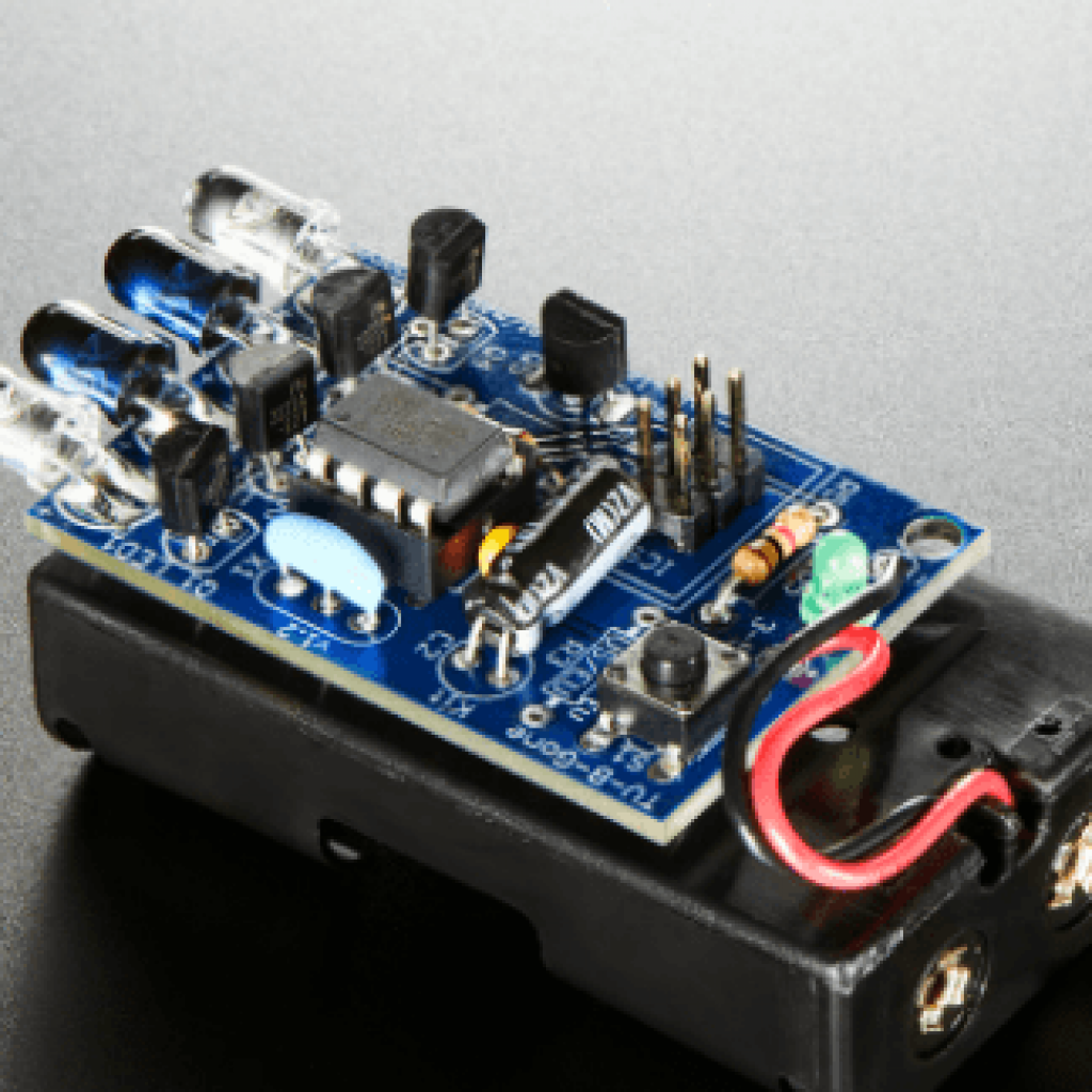
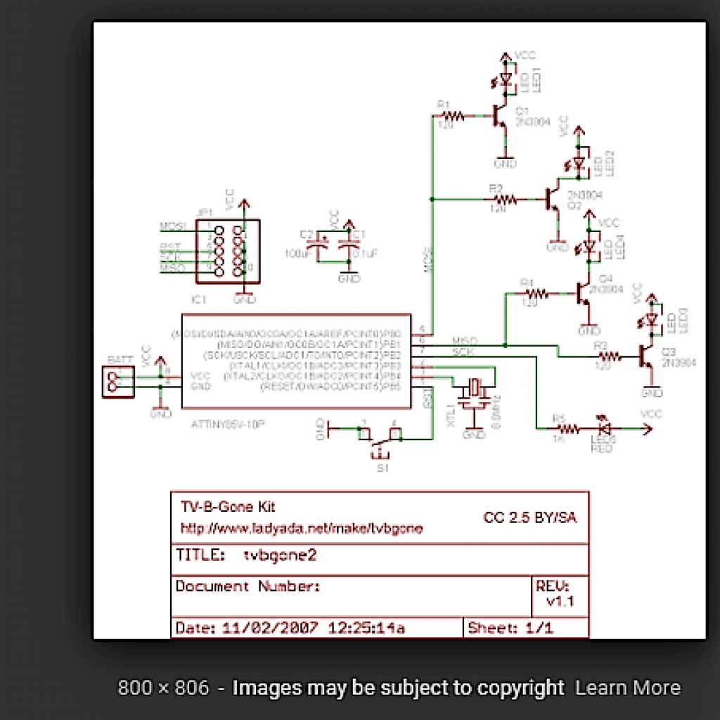
Starter Project
For my starter project I built a Tv B Gone kit by Adafruit. This is basically a remote control that can turn most TV brands on and off. On the kit, there is a button that when you press and release the remote starts transmitting signals of infrared light. There is a green LED light that blinks for every signal sent. After about a minute the remote will automatically shut itself off to save the battery.
How it works:
In this project, there are many electrical components that help to make the project work. The components that was used were leds capacitors, resistors and a microcontroller, the kit there are two different types of light emitted diodes(LEDs). There are wide LEDs that have a short range but have a wider angle to emit the signals. This will turn off TVs close by.There are also the LEDs that are more narrow that have a longer range. This will turn off TVs farther away . The capacitors are like reservoirs that are used to regulate and stabilize energy levels . So if there is a sudden change in the energy supplied by the battery the capacitors are there to give energy to the kit.The resisters control the current flow limiting it and putting it back to normal. In this project all signals are controlled by the microcontroller which is kind of like the computer or brain of the remote.
Challenges:
A problem that I overcame was one of the holes had been filled with solder before I got to use it. The part I needed to go inside of it was a transistor but the transistor pins would not fit inside of it. This was a problem because since the pin could not fit the transistor could not connect to the surface of the circuit board and thus the whole project would not work.
Solutions:
To fix this problem I had to attempt many solutions to get the solder out of the hole. One of the possible solutions that I tried was using the desucker. However the desucker had only worked partly it took the solder that was on top of the hole but not the solder inside the hole. Another solution that I tried was the solder wick. This did not work at all so I had to try something else. The last possibility was to have someone help me while i start melting the solder on one side as they push the pin in on the other side. This came to be the solution that fixed the project and helped me realize that in order to make something great you might need someone else help.